Controller for recreational-vehicle heating system

a controller and heating system technology, applied in the field of recreational vehicle heating systems, can solve the problems of lack of continuous hot water, inability to heat water in relatively long time-consuming for the first class of systems, so as to optimize heating efficiency and cost, and maximize the capability and efficiency of the system heat source.

Inactive Publication Date: 2012-04-19
RIXEN JAMES M
View PDF28 Cites 24 Cited by
  • Summary
  • Abstract
  • Description
  • Claims
  • Application Information

AI Technical Summary

Benefits of technology

[0007]The heating system also includes several programmable features preferably achieved using software incorporated within the controller of the present invention so that each can be adjusted without requiring new hardware, and those features include: (i) a water-heating cycling feature that maximizes the capability and efficiency of the system heat sources by using plural heating solution temperature ranges for automatic actuation/de-actuation of each system heat source depending upon whether the user demands domestic hot water (e.g. system heat source(s) are actuated if water temperature falls below 150° F. and de-actuated if heating solution temperature reaches 180° F.) or area heating (without demand for domestic hot water)(e.g. system heat source(s) are actuated if heating solution temperature falls below 120° F. and de-actuated if heating solution temperature reaches 180° F.), (ii) a heat source priority controller governing situations when different ones of the heating sources of the system are actuated depending upon pre-selected factors such as heating source availability, user-demand requirements, etc.; (iii) an engine preheat loop that allows bi-directional heat transfer...

Problems solved by technology

Drawbacks to this first class include a lack of continuous hot water.
In addition, the first class of systems takes a relatively long period of time to heat water.
Open-flame syst...

Method used


Image

  • Controller for recreational-vehicle heating system
  • Controller for recreational-vehicle heating system
  • Controller for recreational-vehicle heating system

Examples


Embodiment Construction

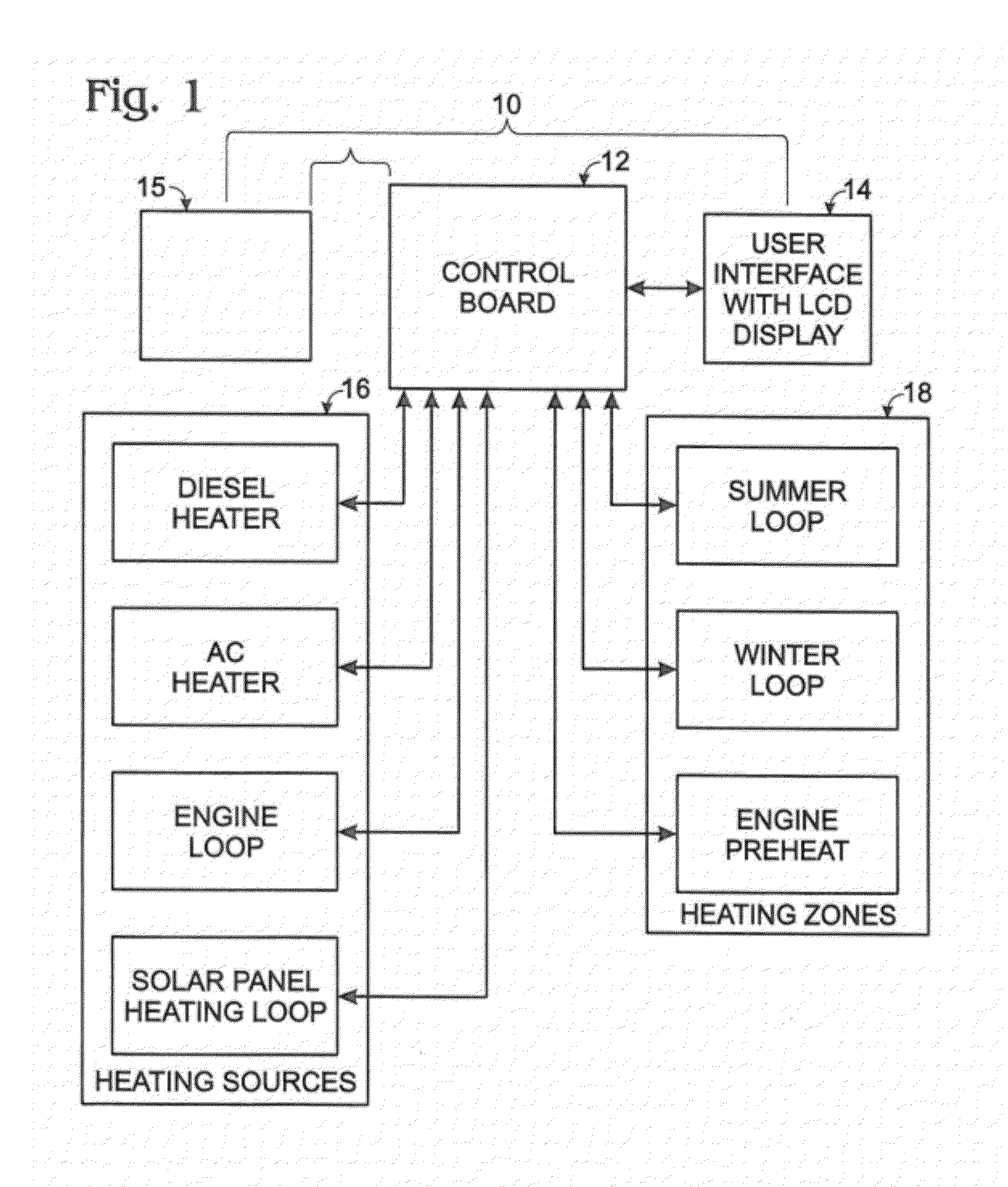
[0018]Referring to FIG. 1, a hydronic heating system including the invention is shown at 10 and includes a controller 12 (with undepicted, suitable, associated control circuitry) in bi-directional electrical / electronic communication with a user interface 14 which can be a part of controller 12 or a separate controller or control panel. User interface 14 can take the form of a display. Controller 12 can also be in fluid / plumbing communication with stand-alone subsystem (SLS) 15. Controller 12 can also be in bi-directional electrical / electronic communication with one or more heating sources 16, and with one or more heating zones 18.

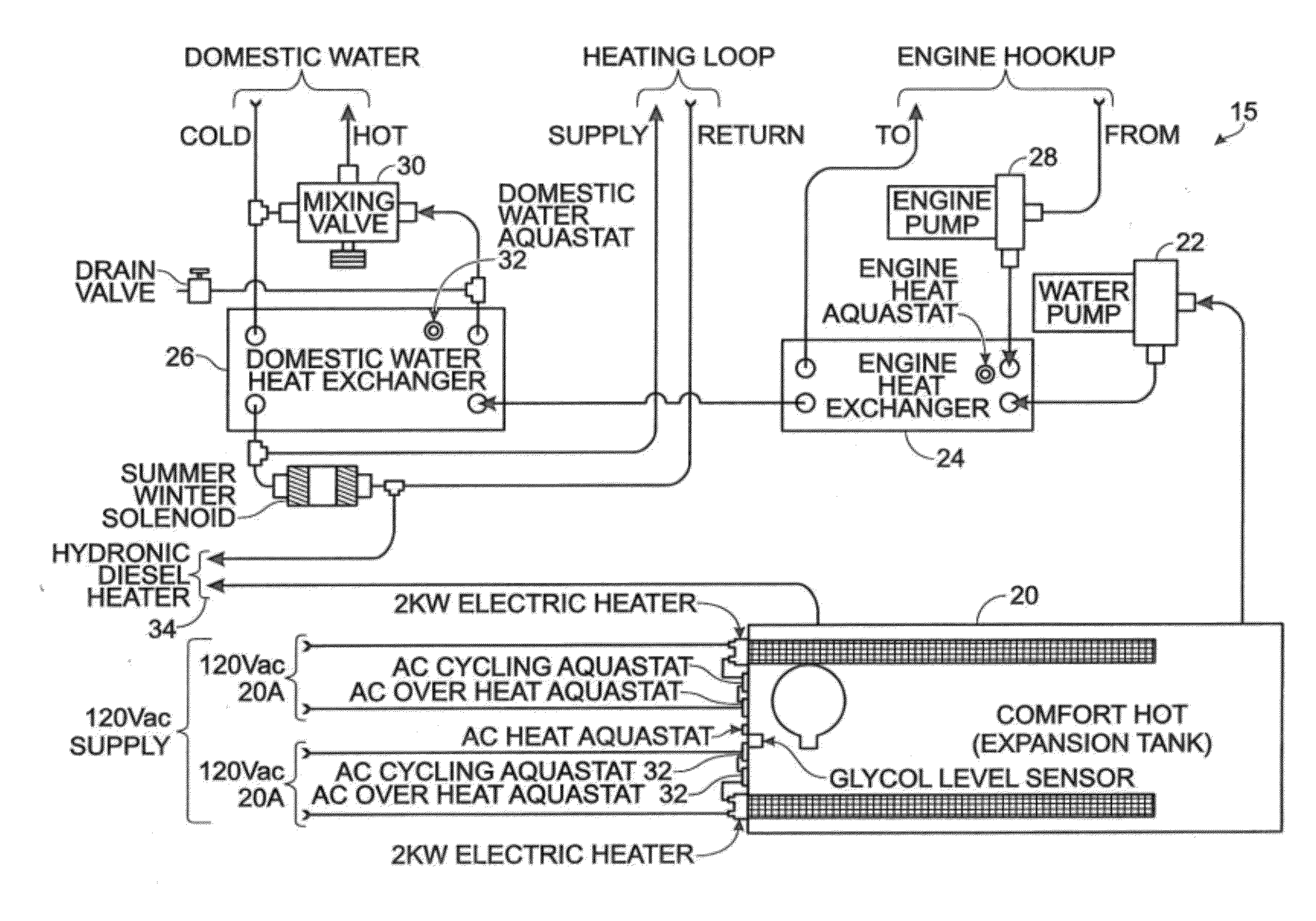
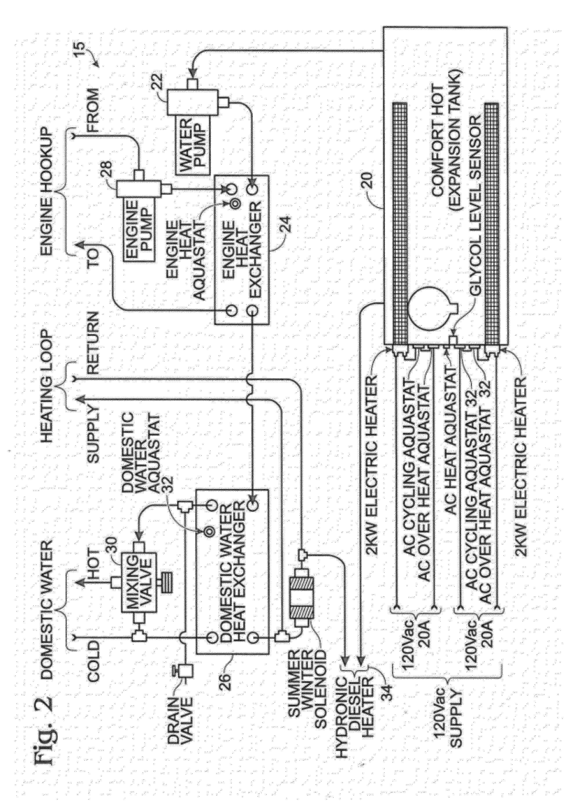
[0019]As shown best in FIGS. 2-3, each of which depict components that are coupled via fluid / plumbing connection, subsystem 15 includes a heating-solution, storage-expansion tank 20 filled with a suitable heating solution (undepicted) such as a commercial grade glycol, a water pump 22, an engine heat exchanger 24, a domestic water heat exchanger 26, a fluid...


PUM


Abstract

A controller in a heat management system is capable of managing unlimited hydronic heat sources and unlimited heating zones, each located within a desired area and each controlled by temperature sensors in bi-directional electronic/electrical communication with the controller. A user interface can be included with the controller (or interact with the controller) and be in bi-directional electrical/electronic communication with the controller. In such a way, one or more users can manage the heating of domestic water and the heating of zones or areas in which the one or more users live via the controller. The controller in the heat management system may be used for controlling hydronic heating systems installed in RV, marine and home applications.

Description

CROSS REFERENCE TO RELATED APPLICATIONS[0001]This application claims the benefit of Rixen, U.S. Provisional Patent Application No. 60 / 774,481, entitled “CONTROLLER FOR RECREATIONAL-VEHICLE HEATING SYSTEM” filed Feb. 16, 2006, which is hereby incorporated by reference herein. This application is a continuation-in-part of Rixen, et al. U.S. patent application Ser. No. 10 / 421,365, entitled “HEATING SYSTEM,” filed Apr. 22, 2003, which is hereby incorporated by reference herein.FIELD OF THE INVENTION[0002]The present invention relates generally to heating systems for recreational vehicles, and more specifically, to a controller for recreational-vehicle heating systems.BACKGROUND OF THE INVENTION[0003]Heating systems for campers and recreational vehicles are widely known. Conventional water heating systems for recreational vehicles generally fall into two classes. The first class includes systems that have a heating element(s) that extends into a cavity that holds several gallons of water...

Claims


Application Information

Patent Timeline
IPC IPC(8): B60H1/02F24D3/08B60H1/22
CPCF23N3/08F23N2025/04F23N2033/08F23N2037/24F24D3/08F24D12/02F24D19/1066F24D2200/14F24D2200/26Y02B10/20Y02B10/70Y02B30/14F24D2200/08B60H1/00364F23N2225/04F23N2233/08F23N2237/24Y02B30/00
Inventor RIXEN, JAMES M.
Owner RIXEN JAMES M
Why Eureka
Try Eureka