Radio communication apparatuses and radio communication method

a radio communication and radio communication technology, applied in the field of radio communication apparatuses and radio communication methods, can solve the problems of inability to set the transmission power required by a base station, increase in cm, and deterioration of data reception performance, so as to correctly switch transmission and suppress the increase of signaling overhead

Active Publication Date: 2012-04-19
SUN PATENT TRUST
View PDF15 Cites 24 Cited by
  • Summary
  • Abstract
  • Description
  • Claims
  • Application Information

AI Technical Summary

Benefits of technology

[0026]According to the present invention, it is possible to suppress increase of signaling overhead and correctly switch transmission modes of a PUSCH and a PUCCH at the same time.

Problems solved by technology

On the other hand, because data is punctured, there is a problem that data reception performance deteriorates.
On the other hand, there is a problem that single carrier characteristics are not maintained and multicarrier transmission is performed, so that CM increases.
When CM increases, the maximum transmission power that can be transmitted by a mobile station lowers, so that power head room (hereinafter referred to as “power head room (PHR)”) of a mobile station located, for example, at the cell edge, becomes small, and it becomes not possible to set the transmission power required by a base station, lowering the reception performance of the base station significantly.
Because a base station cannot determine whether or not a mobile station can correctly receive a command, once a mobile station fails to receive a transmission power control value from a base station, a discrepancy of recognition between the mobile station and the base station occurs.

Method used


Image

  • Radio communication apparatuses and radio communication method
  • Radio communication apparatuses and radio communication method
  • Radio communication apparatuses and radio communication method

Examples


embodiment 1

[0045]FIG. 5 shows a configuration of radio communication mobile station apparatus 100 (hereinafter simply referred to as “mobile station”) according to Embodiment 1 of the present invention. In this figure, RF reception section 102 performs reception processing, such as down-conversion and A / D conversion, on a signal received via antenna 101, and outputs the reception-processed signal to demodulation section 103.

[0046]Demodulation section 103 demodulates scheduling information and a pilot signal that are contained in the reception signal output from RF reception section 102, and outputs the demodulated scheduling information to PHR_data calculation section 104, PHR_control calculation section 106, and transmission mode setting section 107. Further, demodulation section 103 outputs the demodulated pilot signal to PHR_data calculation section 104 and PHR_control calculation section 106.

[0047]PHR_data calculation section 104 calculates PHR_pusch (PHR based on a PUSCH) by performing ca...

embodiment 2

[0106]FIG. 14 is a block diagram showing a configuration of mobile station 300 according to Embodiment 2 of the present invention. FIG. 14 differs from FIG. 5 in that reporting cycle setting section 301 is added, PHR_data report determination section 105 is changed to PHR_data report determination section 302, and trigger information report determination section 108 is changed to trigger information report determination section 303.

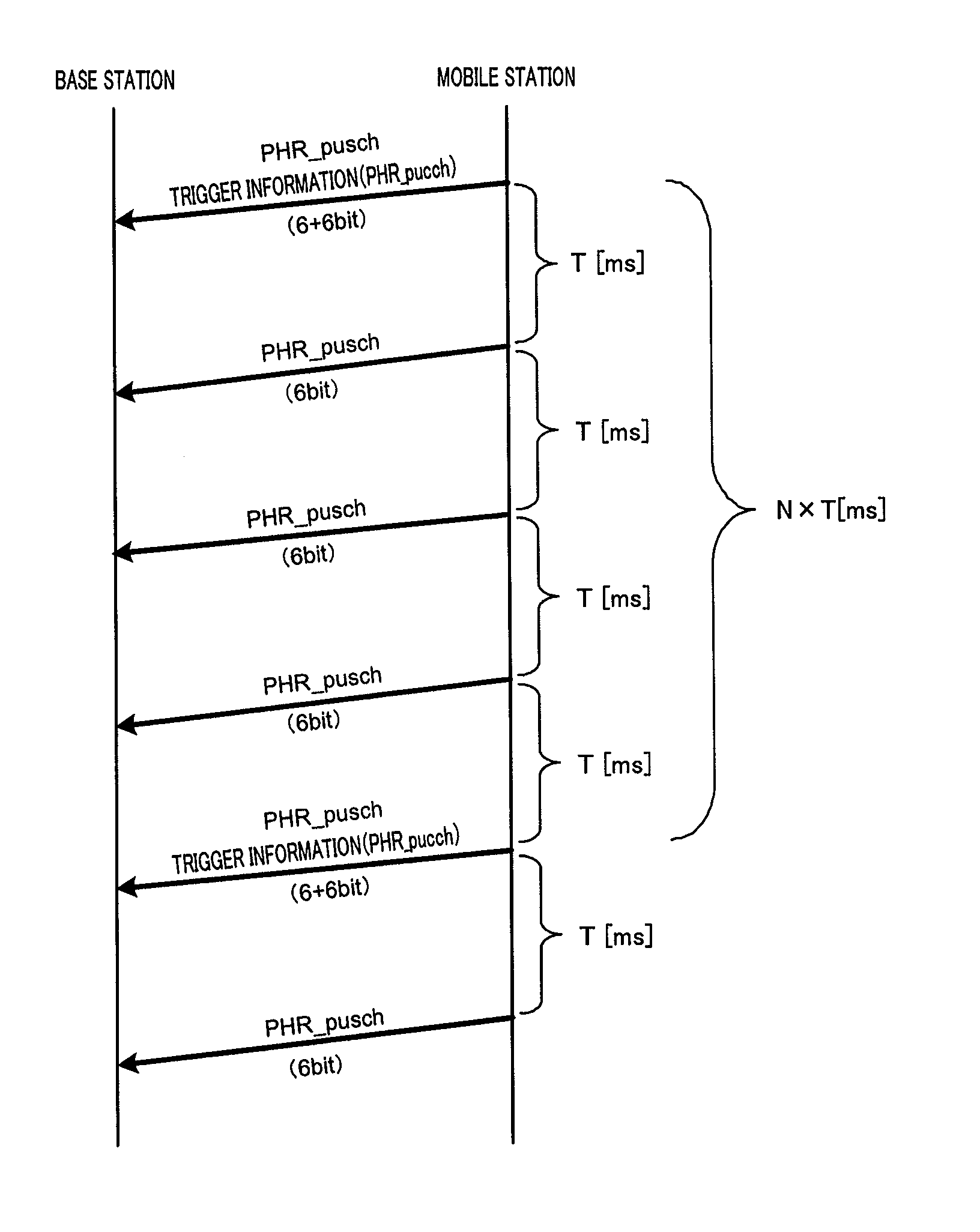
[0107]Reporting cycle setting section 301 sets a reporting cycle of PHR_pusch and a reporting cycle of trigger information so that the reporting cycle of trigger information is longer than the reporting cycle of PHR_pusch, and outputs the set reporting cycle of PHR_pusch to PHR_data report determination section 302 and outputs the reporting cycle of trigger information to trigger information report determination section 303.

[0108]PHR_data report determination section 302 outputs PHR_pusch to data generation section 109, in the cycle output from reporting ...

embodiment 3

[0115]FIG. 16 is a block diagram showing a configuration of mobile station 400 according to Embodiment 3 of the present invention. FIG. 16 differs from FIG. 5 in that PHR_control calculation section 106 is changed to PHR_control calculation section 401, transmission mode setting section 107 is changed to transmission mode setting section 402, PHR_data report determination section 105 is changed to PHR_data report determination section 403, and trigger information report determination section 108 is changed to trigger information report determination section 404.

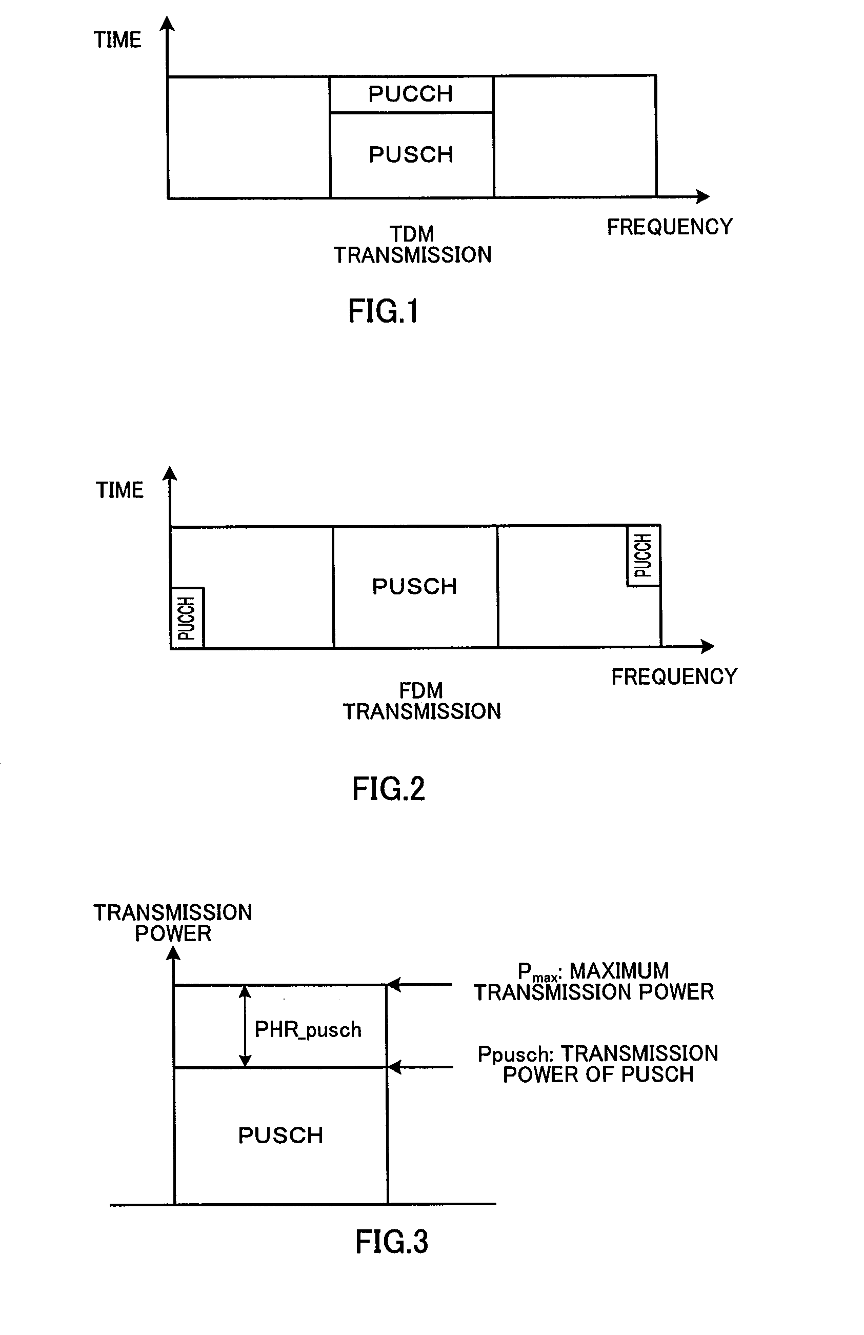
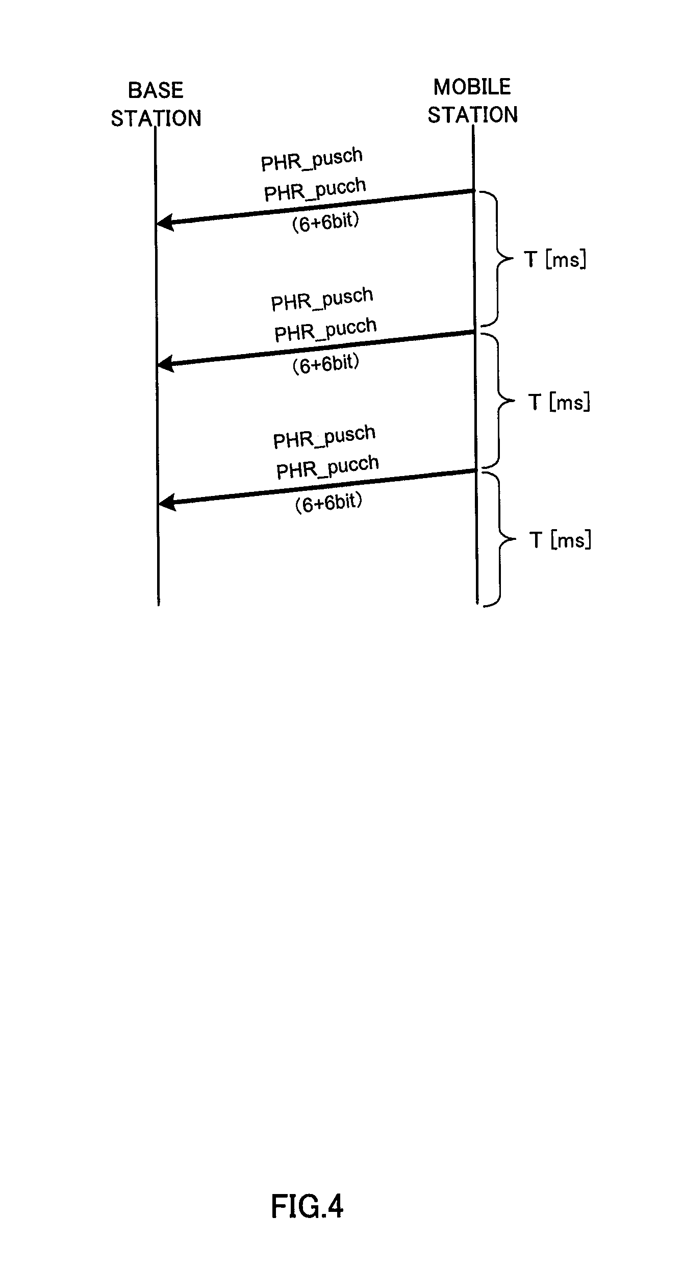
[0116]PHR_control calculation section 401 calculates PHR_pusch+pucch (PHR calculated based on transmission power required when a data channel and a control channel are FDM transmitted, as a reference) and PHR_pucch, based on a path loss level measured using a downlink pilot signal output from demodulation section 103, and the number of frequency resource blocks of a PUSCH, the MCS, power control information of a PUSCH, and po...


PUM


Abstract

Provided are a radio communication mobile station apparatus, a radio communication base station apparatus and a radio communication method, which make it possible to correctly switch between transmission modes for a PUSCH and a PUCCH while impeding signaling overhead from increasing. A transmission mode setting unit (107) detects an instruction given by a base station, the instruction indicating a multiplexing method for a PUSCH and a PUCCH. A trigger information reporting determination unit (108) performs threshold discrimination where PHR_pucch, which is calculated by PHR_control calculation unit (106), is compared with a threshold value that depends on the multiplexing method indicated by the instruction given by the base station. Specifically, in a TDM transmission mode, trigger information is reported if PHR_pucch>X1[dBm] is satisfied. On the other hand, in an FDM transmission mode, the trigger information is reported if PHR_pucch<Y1[dBm] is satisfied. Based on a result of the threshold discrimination, the trigger information reporting determination unit (108) determines whether to report the trigger information.

Description

TECHNICAL FIELD[0001]The present invention relates to a radio communication apparatus and a radio communication method.BACKGROUND ART[0002]In 3rd Generation Partnership Project Long-term Evolution (3GPP LTE), in the case where a data channel (physical uplink shared channel (PUSCH)) and a control channel (physical uplink control channel (PUCCH)) are transmitted in the same subframe, a mobile station multiplexes the two channels by time division multiplexing (TDM), as shown in FIG. 1. That is, data is punctured by control information such as an ACK or a NACK. By TDM multiplexing, it is possible to maintain single carrier characteristics and prevent increase of cubic metric (CM). On the other hand, because data is punctured, there is a problem that data reception performance deteriorates.[0003]In an uplink channel of LTE-Advanced, which is an evolved version of 3GPP LTE, in the case where a PUSCH and a PUCCH are transmitted in the same subframe, a mobile station is expected to multiple...

Claims


Application Information

Patent Timeline
Patent Type & Authority Applications(United States)
IPC IPC(8): H04W24/00
CPCH04L5/0053H04L5/0007H04L1/0025H04W52/365H04W72/53H04W72/0473
Inventor IWAI, TAKASHINISHIO, AKIHIKOIMAMURA, DAICHIOGAWA, YOSHIHIKOMATSUMOTO, ATSUSHI
Owner SUN PATENT TRUST
Why Eureka
Try Eureka