High-speed optical sampling by temporal stretching using four-wave mixing

a temporal stretching and optical sampling technology, applied in electromagnetic transmission, electrical equipment, instruments, etc., can solve the problems of limited sampling rate of 60 gs/s, inability to sample short optical packets, and inability to operate single-sho

Active Publication Date: 2012-04-19
CORNELL UNIVERSITY
View PDF15 Cites 27 Cited by
  • Summary
  • Abstract
  • Description
  • Claims
  • Application Information

AI Technical Summary

Problems solved by technology

Photodiodes are currently used in conjunction with real-time oscilloscopes; however the sampling rate is limited to 60 GS/s, which is capable of processing signals with up to 30 GHz bandwidth.
These systems, however, cannot operate single-shot and therefore cannot sample short optical packets or work with non-repetitive waveforms.
Autocorrelation and cross-correlation may also be used, however the optical signal must be deduced from the result and a single shot measurement is not possible over record lengths longer than a few picoseconds.
Other known methods include Frequency Resolved Optical Gating (FROG) and Spectral Phase Interferometry for Direct Electric-field Reconstruction (SPIDER), However, the record length for single-shot characterization using these techniques is limited to a couple of picoseconds.
The traditional o

Method used


Image

  • High-speed optical sampling by temporal stretching using four-wave mixing
  • High-speed optical sampling by temporal stretching using four-wave mixing
  • High-speed optical sampling by temporal stretching using four-wave mixing

Examples


example 1

6.1 Example 1

Silicon-Chip-Based Ultrafast Optical Oscilloscope

Introduction

[0200]This example demonstrates the general principles configuration, design and function of a silicon-chip-based ultrafast optical oscilloscope. These general principles can be applied to the temporal stretching systems and methods, as disclosed hereinabove and in Example 3 (for high-speed optical sampling using a silicon-chip temporal magnifier).

[0201]With the realization of faster telecommunication data rates and expanding interest in ultrafast chemical and physical phenomena, simple measurements of optical waveforms with sub-picosecond resolution is increasingly important (C. Dorrer, High-speed measurements for optical telecommunication systems, IEEE J. Sel. Top. Quantum Electron. 12, 843-858 (2006)). State-of-the-art oscilloscopes with high-speed photodetectors provide single-shot waveform measurement with 30-ps resolution. While multiple-shot sampling techniques can achieve few-picosecond resolution, sin...

example 2

6.2 Example 2

Optical Time Lens Based on Four-Wave Mixing (FWM) on a Silicon Chip

[0232]This example demonstrates the general principles of configuration, design and function of an optical time lens based on four-wave mixing (FWM) on a silicon chip. These general principles can be applied to the methods and system for high-speed optical sampling using a silicon-chip temporal magnifier, as disclosed hereinabove and in Example 3.

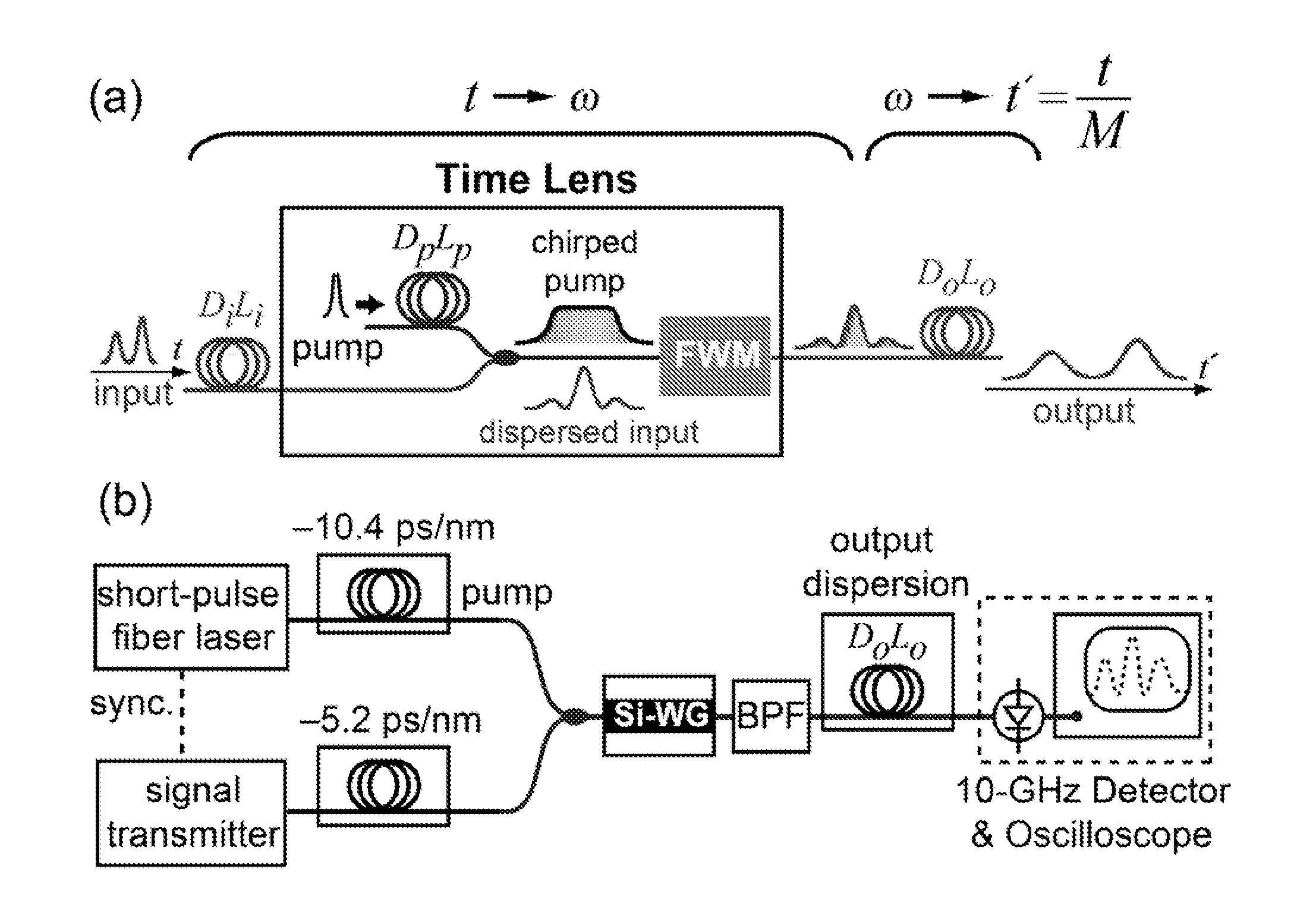
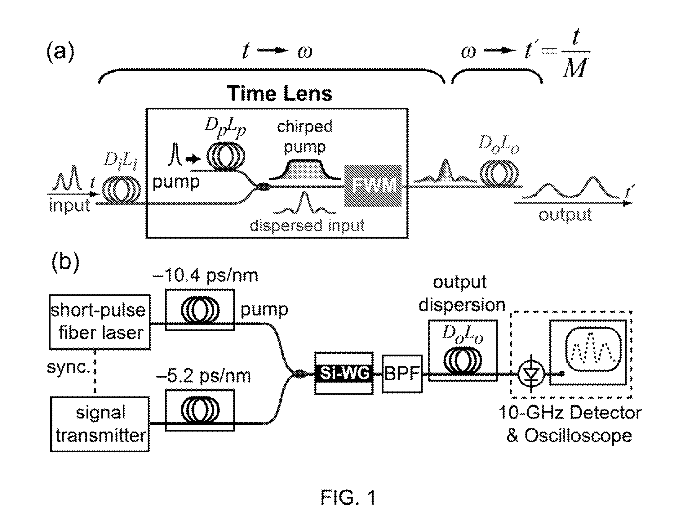
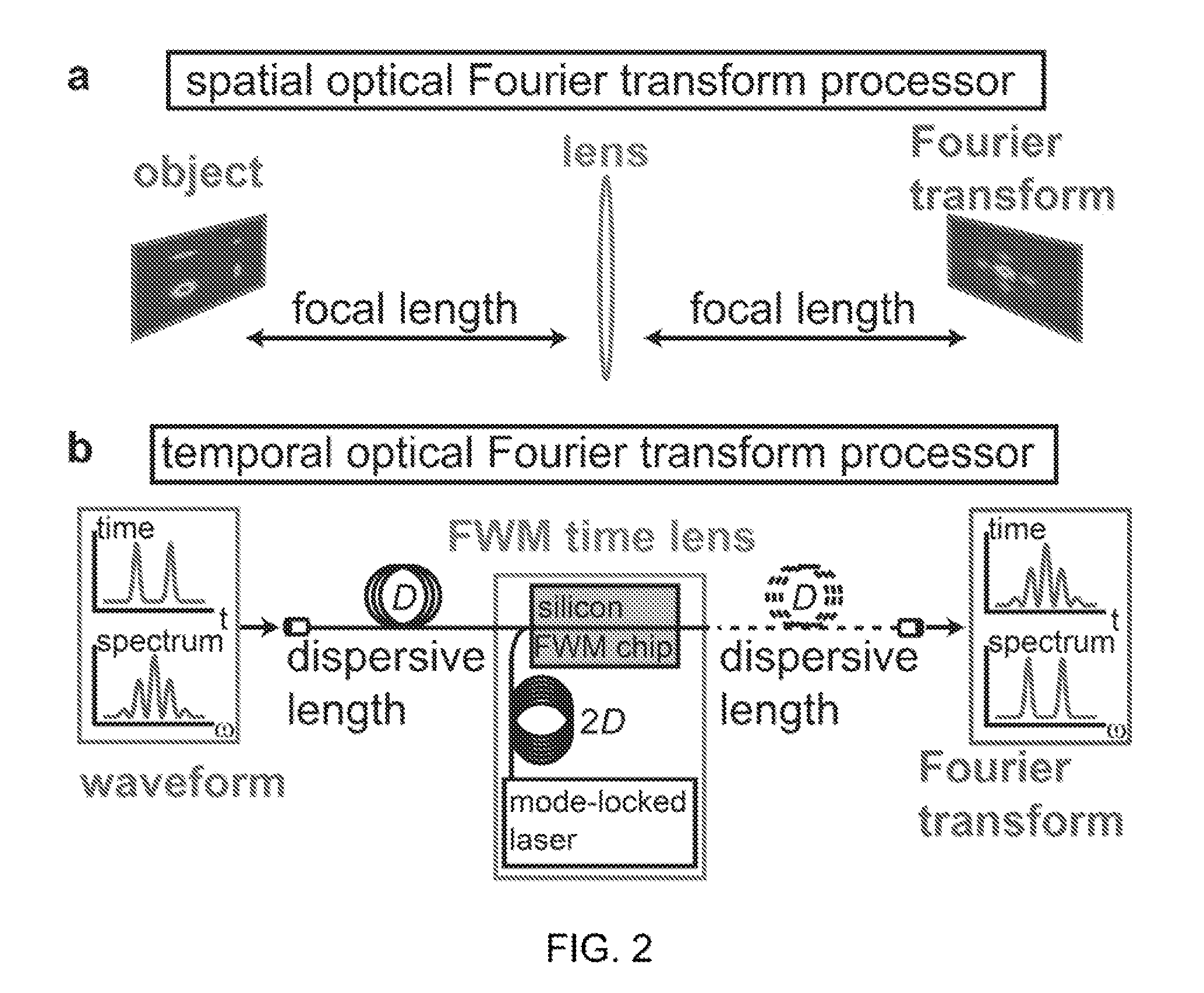
[0233]The example demonstrates a technique to realize an optical time lens for ultrafast temporal processing that is based on four-wave mixing in a silicon nanowaveguide. The demonstrated time lens produces more than 100π of phase shift, which is not readily achievable using electro-optic phase modulators. Using this method 20× magnification of a signal consisting of two 3 ps pulses is demonstrated, which allows for temporal measurements using a detector with a 20 GHz bandwidth. The technique offers the capability of ultrafast temporal characterization and proce...

example 3

6.3 Example 3

High-Speed Optical Sampling Using a Silicon-Chip Temporal Magnifier

[0242]This example demonstrates the utility of a FWM-based time lens for temporal stretching of high-speed signals by factors as large as 520, such that the sampling can be performed using low-speed electronic devices. It also demonstrates single-shot sampling at sampling rates exceeding 1 TS / s and performance monitoring at 80 Gb / s as two important applications of this device. The read-out rates achieved using this scheme approach nanosecond time scales, which allows for characterization of rapidly-varying signals. The implementation described in this example is a fully-guided system that utilizes a silicon nanowaveguide, based on the CMOS-compatible silicon-on-insulator technology, and commercially-available single-mode optical fibers. In addition to their robust and electronics-compatible platform with a standard fabrication process, silicon waveguide devices allow power-efficient (R. L. Espinola, J. I...


PUM


Abstract

Systems and methods are provided for ultrafast optical waveform sampling based on temporal stretching of an input signal waveform. Temporal stretching is performed using a time lens based on four-wave mixing in a nonlinear medium. The signal is passed through an input dispersive element. The dispersed signal is sent into the time lens, which comprises a chirped pump pulse and a nonlinear medium. The chirped pump pulse is combined with the signal. The four-wave mixing process occurs in the nonlinear device or medium, which results in the generation of a signal at a new optical frequency (idler). The idler is spectrally separated from the signal and pump pulse using a bandpass filter and sent into an output dispersive element. The output dis persive element is longer than the input dispersive element and the temporal stretching factor is given by the ratio between the dispersions of these two elements.

Description

CROSS-REFERENCE TO RELATED APPLICATIONS[0001]This application claims priority to and the benefit of co-pending U.S. provisional patent application Ser. No. 61 / 150,270, entitled High-Speed Optical Sampling by Temporal Stretching Using Four-Wave Mixing, by Lipson et al., filed Feb. 5, 2009, which is incorporated herein by reference in its entirety.STATEMENT REGARDING FEDERALLY SPONSORED RESEARCH OR DEVELOPMENT[0002]The disclosed invention was made with government support under the DSO OAWG Program from DARPA and under a grant to the Center for Nanoscale Systems from the National Science Foundation. The government has rights in this invention.1. TECHNICAL FIELD[0003]The present invention relates to methods and devices for ultrafast optical waveform sampling based on temporal stretching of an input signal waveform.2. BACKGROUND OF THE INVENTION[0004]Photodiodes are currently used in conjunction with real-time oscilloscopes; however the sampling rate is limited to 60 GS / s, which is capab...

Claims


Application Information

Patent Timeline
IPC IPC(8): H04B10/00H04B15/00
CPCG01J11/00
Inventor LIPSON, MICHALGAETA, ALEXANDERSALEM, REZAFOSTER, MARKGERAGHTY, DAVIDFOSTER, AMY
Owner CORNELL UNIVERSITY
Why Eureka
Try Eureka