
Metal Foil with Electric Resistance Film and Production Method Thereof

a technology of resistance film and metal foil, which is applied in the field of metal foil, can solve the problems of deterioration in quality, inability to discover the correlation between surface roughness of copper foil and fluctuation, and inability to detect the fluctuation or fluctuation of resistance value, so as to inhibit the fluctuation or variation of resistance value and facilitate the adhesive

Inactive Publication Date: 2012-04-19
JX NIPPON MINING& METALS CORP
View PDF2 Cites 6 Cited by
  • Summary
  • Abstract
  • Description
  • Claims
  • Application Information

AI Technical Summary

Benefits of technology

[0031]The present invention yields superior effects of being able to obtain a copper foil comprising an electric resistance film possessing favorable adhesiveness and capable of inhibiting the fluctuation or variation of the resistance value, which are drawbacks associated with a copper foil with an electric resistance film built therein.

Problems solved by technology

Nevertheless, if the surface roughness is increased in order to achieve the foregoing peel strength, there is a problem in that the resistance value will vary considerably.
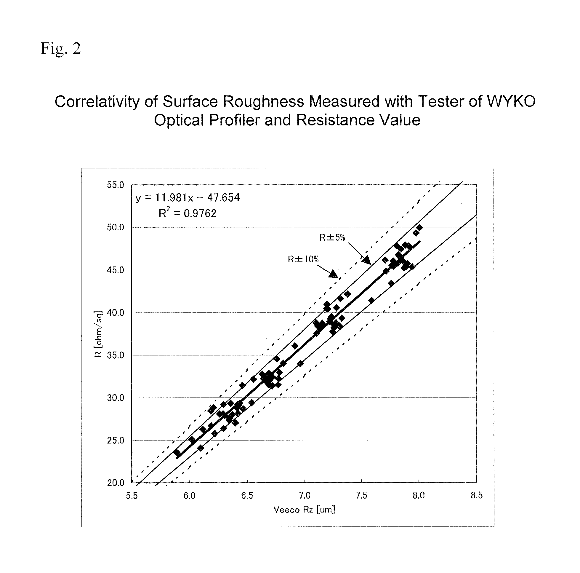
Conventionally, measurement of the surface roughness of the copper foil has been performed with the stylus method prescribed in JISB0601, but with this method, it is not possible to discover the correlation of the surface roughness of the copper foil and the fluctuation or variation of the electric resistance value of the resistance film.
Nevertheless, if the resistance value of the resistance layer formed on the copper foil is subject to fluctuation or variation, this is not a favorable state since it will cause deterioration in the quality upon forming the resistance layer on a substrate with an electric resistance film built therein.

Method used

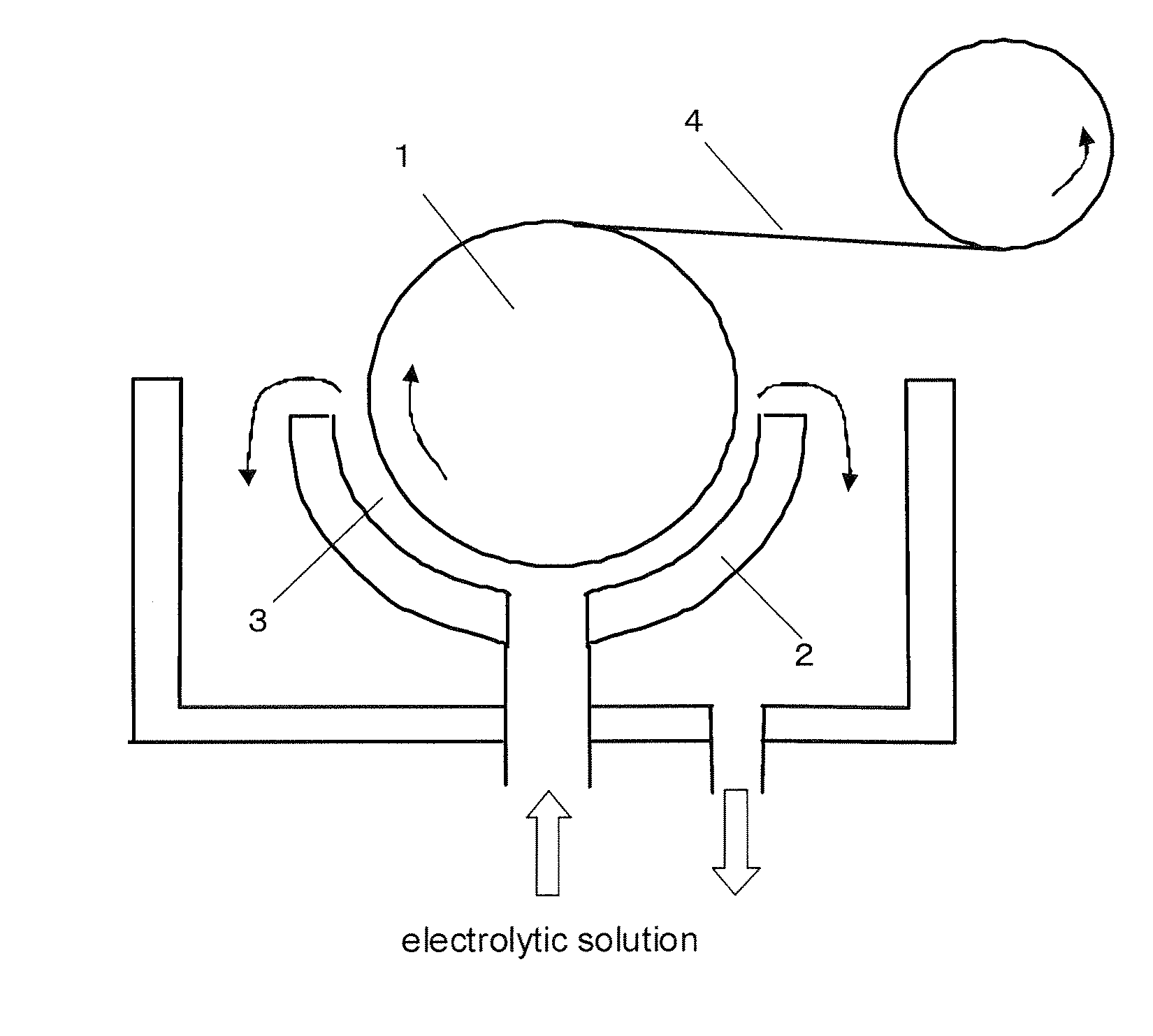
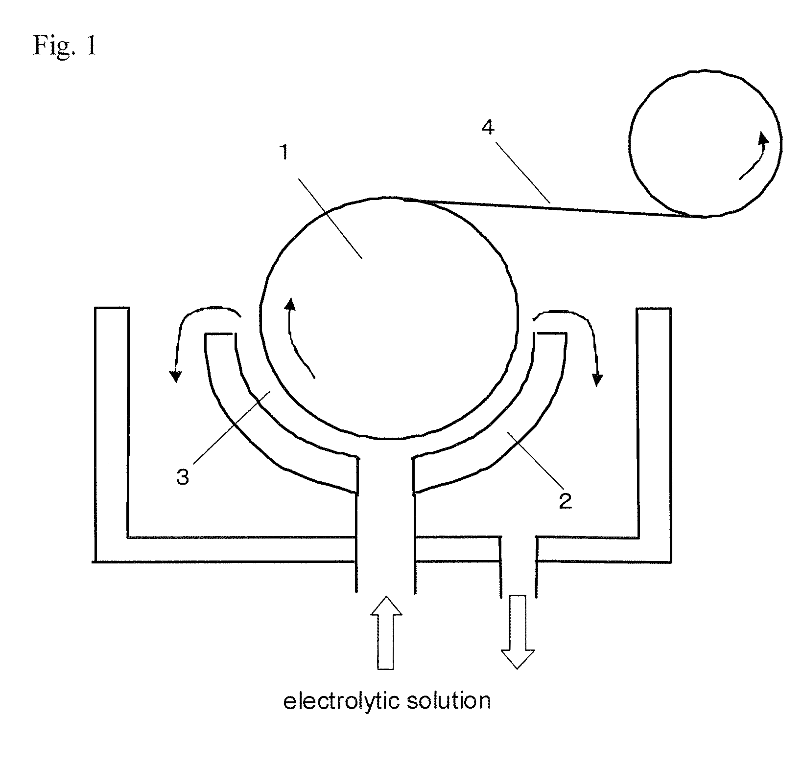

Image

  • Metal Foil with Electric Resistance Film and Production Method Thereof
  • Metal Foil with Electric Resistance Film and Production Method Thereof
  • Metal Foil with Electric Resistance Film and Production Method Thereof

Examples


example 1

[0071]In Example 1, an electrolytic copper foil having a thickness of 18 μm was used. Roughening treatment was performed to the rough surface (matted surface) side of the electrolytic copper foil. The roughening treatment was performed for 3 seconds at a current density of 42 A / dm2 under the foregoing roughening plating conditions.

[0072]The fluctuation of the surface roughness caused by the temperature, carrier speed, electrolytic solution and other statuses was controlled by adjusting the treatment time, and a roughened electrolytic copper foil having a 10-point average roughness Rz of 6.3 μm and a variation of ±5% was prepared. The results are shown in Table 1.

TABLE 1NormalHeatCurrentPeelResistanceDensityRzVariationValuePeel Value(A / dm2)(μm)of Rz (%)(kN / m)(kN / m)Example 1426.350.670.65Example 2496.740.840.80Example 3557.241.060.99Example 4637.941.171.09Comparative—5.130.290.27Example 1

[0073]Subsequently, the roughened electrolytic copper foil was used, and an electric resistance ma...

example 2

[0081]In Example 2, an electrolytic copper foil having a thickness of 18 μm was used. Roughening treatment was performed to the rough surface (matted surface) side of the electrolytic copper foil. The roughening treatment was performed for 3 seconds at a current density of 49 A / dm2 under the foregoing roughening plating conditions.

[0082]The fluctuation of the surface roughness caused by the temperature, carrier speed, electrolytic solution and other statuses was controlled by adjusting the treatment time, and a roughened electrolytic copper foil having a 10-point average roughness Rz of 6.7 μm and a variation of ±4% was prepared. The results are similarly shown in Table 1.

[0083]Subsequently, the same electric resistance material as Example 1 was attached to the stabilization layer under the same conditions. Consequently, in the case of Example 2 that used a roughened electrolytic copper foil of Rz 6.7 μm, the sheet resistivity of the resistance material was 32 Ω / sq (square), and the...

example 3

[0085]In Example 3, an electrolytic copper foil having a thickness of 18 μm was used. Roughening treatment was performed to the rough surface (matted surface) side of the electrolytic copper foil. The roughening treatment was performed for 3 seconds at a current density of 55 A / dm2 under the foregoing roughening plating conditions.

[0086]The fluctuation of the surface roughness caused by the temperature, carrier speed, electrolytic solution and other statuses was controlled by adjusting the treatment time, and a roughened electrolytic copper foil having a 10-point average roughness Rz of 7.2 μm and a variation of ±4% was prepared. The results are similarly shown in Table 1.

[0087]Subsequently, the same electric resistance material as Example 1 was attached to the stabilization layer under the same conditions. Consequently, in the case of Example 2 that used a roughened electrolytic copper foil of Rz 7.2 μm, the sheet resistivity of the resistance material was 38 Ω / sq (square), and the...


PUM


Abstract

A metal foil comprising an electric resistance film in which the metal foil is made of copper or copper alloy, the surface roughness of at least one surface thereof is set to a 10-point average roughness Rz of 6.0 μm to 8.0 μm, and an electric resistance film is formed on that surface, wherein the peel strength of the electric resistance film is 0.60 kN / m or more, and variation of the resistance value of the electric resistance film is ±10% or less. Provided is a copper foil with an electric resistance film in which an electric resistance film is formed on the copper foil to enable the resistor to be built into the substrate, the adhesiveness thereof to a resin substrate is ensured, and variation of the resistance value of the electric resistance film is reduced.

Description

TECHNICAL FIELD[0001]The present invention relates to a metal foil made of copper or copper alloy with an electric resistance film having high peel strength and low variation of the electric resistance value, and to a method of producing the same.[0002]In the foregoing case, since the electric resistance film is of a layered structure with the copper foil, it can also be deemed an “electric resistance layer,” but in this specification, this is referred to as an “electric resistance film” inclusive of the foregoing meaning.[0003]Moreover, a metal foil made of copper or copper alloy can generally be classified as an electrolytic copper foil or a rolled copper foil, but in the present invention these are collectively referred to as a “copper foil.” In addition, although these can also be classified as a copper foil or a copper alloy foil, these are also collectively referred to as a “copper foil.” As described above, unless specifically identified and referred to, these are indicated a...

Claims


Application Information

Patent Timeline
Patent Type & Authority Applications(United States)
IPC IPC(8): B32B15/04C25D5/34B32B15/01B05D5/12C23C14/06B32B5/00C25F3/02B05D3/14
CPCB32B15/01C23C14/02C23C14/165C23C14/562C23C28/023C25D7/0614Y10T428/266H05K3/022H05K2201/0355H05K2203/0307H05K2203/0361C23C28/021C23C28/022H05K1/167Y10T428/31678B32B15/20C23C28/02C25D7/06
Inventor KUROSAWA, TOSHIO
Owner JX NIPPON MINING& METALS CORP
Learn More