
Battery module having heat dissipation member of novel structure and battery pack employed with the same

Active Publication Date: 2012-04-19
LG ENERGY SOLUTION LTD
View PDF3 Cites 29 Cited by
  • Summary
  • Abstract
  • Description
  • Claims
  • Application Information

AI Technical Summary

Benefits of technology

[0013]Specifically, it is an object of the present invention to provide a battery module configured in a structure in which coolant channels are minimally formed, and high thermal conductivity is achieved by a specific structure of heat dissipation members, thereby achieving uniform temperature of the battery module while restricting the increase in size of the battery module and thus reducing temperature deviation.Technical Solution
[0051]The battery pack according to the present invention includes a plurality of battery cells in order to provide high power and large capacity. Consequently, the battery pack according to the present invention is preferably used as a power source for electric vehicles, hybrid electric vehicles, or plug-in hybrid electric vehicles in which high-temperature heat generated during the charge and discharge of the battery cells is a serious safety concern.

Problems solved by technology

Consequently, a large amount of heat is generated from the high-power, large-capacity secondary batteries during the charge and discharge of the batteries.
In particular, the laminate sheet of each pouch-shaped battery widely used in the battery module has a polymer material exhibiting low thermal conductivity coated on the surface thereof with the result that it is difficult to effectively lower the overall temperature of the battery cells.
That is, if the heat, generated from the battery module during the charge and discharge of the battery module, is not effectively removed from the battery module, the heat accumulates in the battery module with the result that deterioration of the battery module is accelerated.
According to circumstances, the battery module may catch fire or explode.
In this structure, however, it is necessary to provide a plurality of coolant channels corresponding to the number of the battery cells with the result that the overall size of the battery module is increased.
As a result, design of the cooling structure is complicated.
That is, high pressure loss is caused by the coolant channels arranged at intervals narrower than a coolant inlet port with the result that it is difficult to design shapes and positions of the coolant inlet port and a coolant outlet port.
Also, a fan may be further provided to prevent such pressure loss, and therefore, design may be restricted due to power consumption, fan noise, space or the like.
Furthermore, desired cooling efficiency may not be achieved due to the same thickness of members used in designing the cooling structure or spaces defined between the members.

Method used


Image

  • Battery module having heat dissipation member of novel structure and battery pack employed with the same
  • Battery module having heat dissipation member of novel structure and battery pack employed with the same
  • Battery module having heat dissipation member of novel structure and battery pack employed with the same

Examples


experimental example 1

[0100]A battery module manufactured according to Example 1 and a battery module manufactured according to Comparative example 1 were prepared, and the change in temperature of the battery module based on heat generated from the battery cells of the respective battery module was measured. The results were indicated in FIGS. 12, 13 and 14 (a graph). This experiment was carried out in a condition in which heat is generated from the battery module including the heat dissipation member at room temperature for 5 minutes.

[0101]As can be seen from FIG. 12, the heat dissipation member was shown in a blue color in the temperature change experiment carried out with respect to the battery module of Example 1 according to the present invention. In particular, the upper parts of the battery cells adjacent to the connection part of the heat dissipation member had lower temperature than the lower parts of the battery cells. For reference, a blue color indicates low temperature while a red color ind...


PUM


Abstract

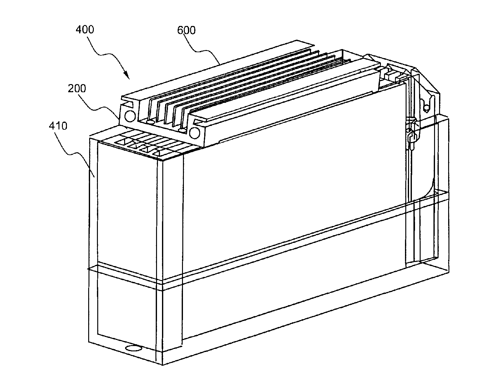
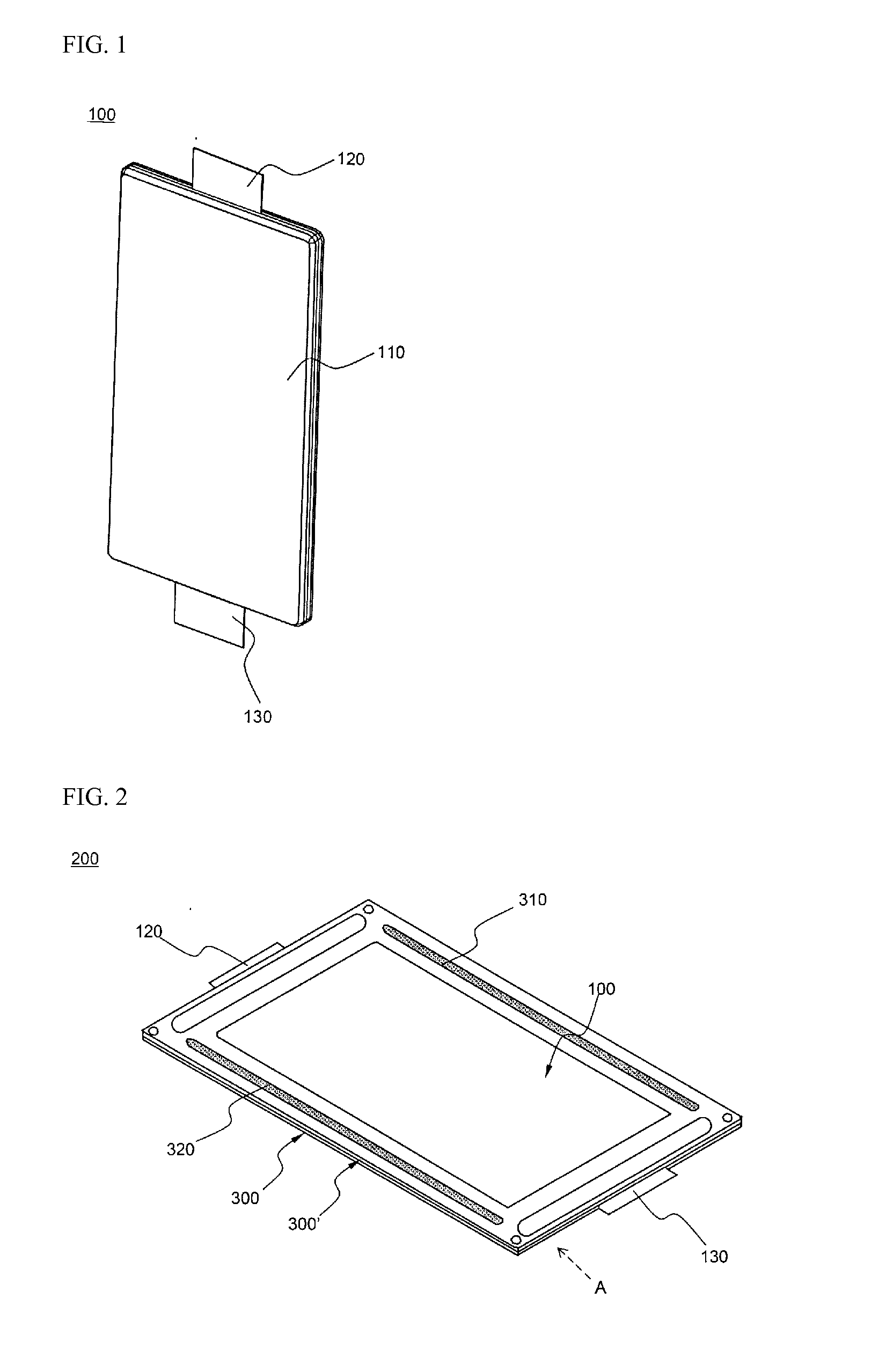
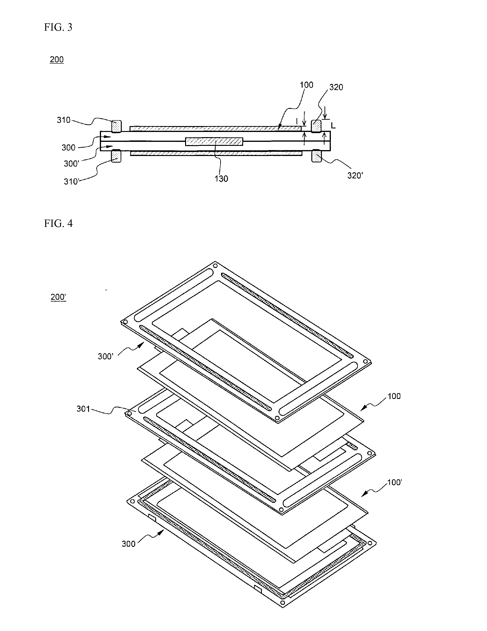
Disclosed is a battery module including a plurality of plate-shaped battery cells mounted in a module case in a stacked state, wherein each of the plate-shaped battery cells is configured in a structure in which an electrode assembly is mounted in a battery case formed of a laminate sheet, the battery module is configured in a structure in which a plurality of heat dissipation members disposed at two or more interfaces between the battery cells and a heat exchange member to integrally interconnect the heat dissipation members are mounted at one side of a battery cell stack, and heat generated from the battery cells during charge and discharge of the battery cells is removed by the heat exchange member via the heat dissipation members.

Description

TECHNICAL FIELD[0001]The present invention relates to a battery module having a heat dissipation member of a novel structure and a middle or large-sized battery pack including the same, and, more particularly, to a battery module including a plurality of plate-shaped battery cells mounted in a module case in a stacked state, wherein the battery module is configured in a structure in which a plurality of heat dissipation members disposed at two or more interfaces between the battery cells and a heat exchange member to integrally interconnect the heat dissipation members are mounted at one side of a battery cell stack, and heat generated from the battery cells during charge and discharge of the battery cells is removed by the heat exchange member, and each of the heat dissipation members includes a main body part, a connection part and a top part.BACKGROUND ART[0002]Recently, a secondary battery, which can be charged and discharged, has been widely used as an energy source for wireles...

Claims


Application Information

Patent Timeline
IPC IPC(8): H01M10/50H01M50/211
CPCB60L11/1874B60L11/1879H01M2/1072H01M10/0413Y02T10/705H01M10/5016H01M10/5032H01M10/5053Y02T10/7005H01M10/5004H01M10/625H01M10/647H01M10/6554H01M10/613B60L58/26B60L50/64Y02T10/70Y02E60/10Y02P70/50H01M50/211H01M50/124H01M10/653H01M10/6556H01M50/129H01M50/20H01M2220/20
Inventor LEE, JINKYUYOON, HEE SOOLEE, BUMHYUNKANG, DAL MOKIM, MINJUNG
Owner LG ENERGY SOLUTION LTD
Learn More