Effect-driven specification of dynamic lighting

a dynamic lighting and effect-driven technology, applied in the field of design tools, can solve the problems of time-consuming process and discourage new users, and achieve the effects of maximizing agreement, improving support, and easily displaying such details within the user interfa

Active Publication Date: 2012-04-19
SIGNIFY HLDG BV
View PDF3 Cites 45 Cited by
  • Summary
  • Abstract
  • Description
  • Claims
  • Application Information

AI Technical Summary

Benefits of technology

[0027]A design tool according to the invention may not only assist the user in bridging the gap between lighting effects and realizations of these, but may also simulate the deployment of the implementation options in the environment. More precisely, if the environment is encoded as a three-dimensional model, possibly including natural light sources and the like, artificial light sources corresponding to the implementation options can easily be added to the model. By examining the resulting three-dimensional model from suitable viewpoints, the user can subjectively assess the agreement with the intended light effect and base his or her selection of an implementation option on this.
[0029]In other embodiments of the invention, all or part of the selection of implementation options is carried out automatically. A preferred way of performing such automatic selection is by ranking the implementation options associated with one lighting effect according to a quality index. The quality index may be based on visual properties, an agreement metric or other properties. For example, the quality index could be the energy consumption per unit time (thus optimizing the operational economy), the purchase price (thus minimizing the initial expenditure), the expected useful life of each device (thus maximizing the lifetime) or the term of delivery (thus favoring a swift setup). Conceivable is also an index that minimizes the deviation between individual device lifetimes, so that the entire installation can be decommissioned at a future point in time when the total residual lifetime is as small as possible, which is economically desirable.

Problems solved by technology

Such a device-oriented design interface forces the user into thinking in terms of existing devices and their capabilities, not in terms of what would be desirable aesthetically or functionally.
Acquiring and maintaining sufficient familiarity with lighting device available from suppliers may however be a time-consuming process that discourages fresh users.

Method used


Image

  • Effect-driven specification of dynamic lighting
  • Effect-driven specification of dynamic lighting
  • Effect-driven specification of dynamic lighting

Examples


Embodiment Construction

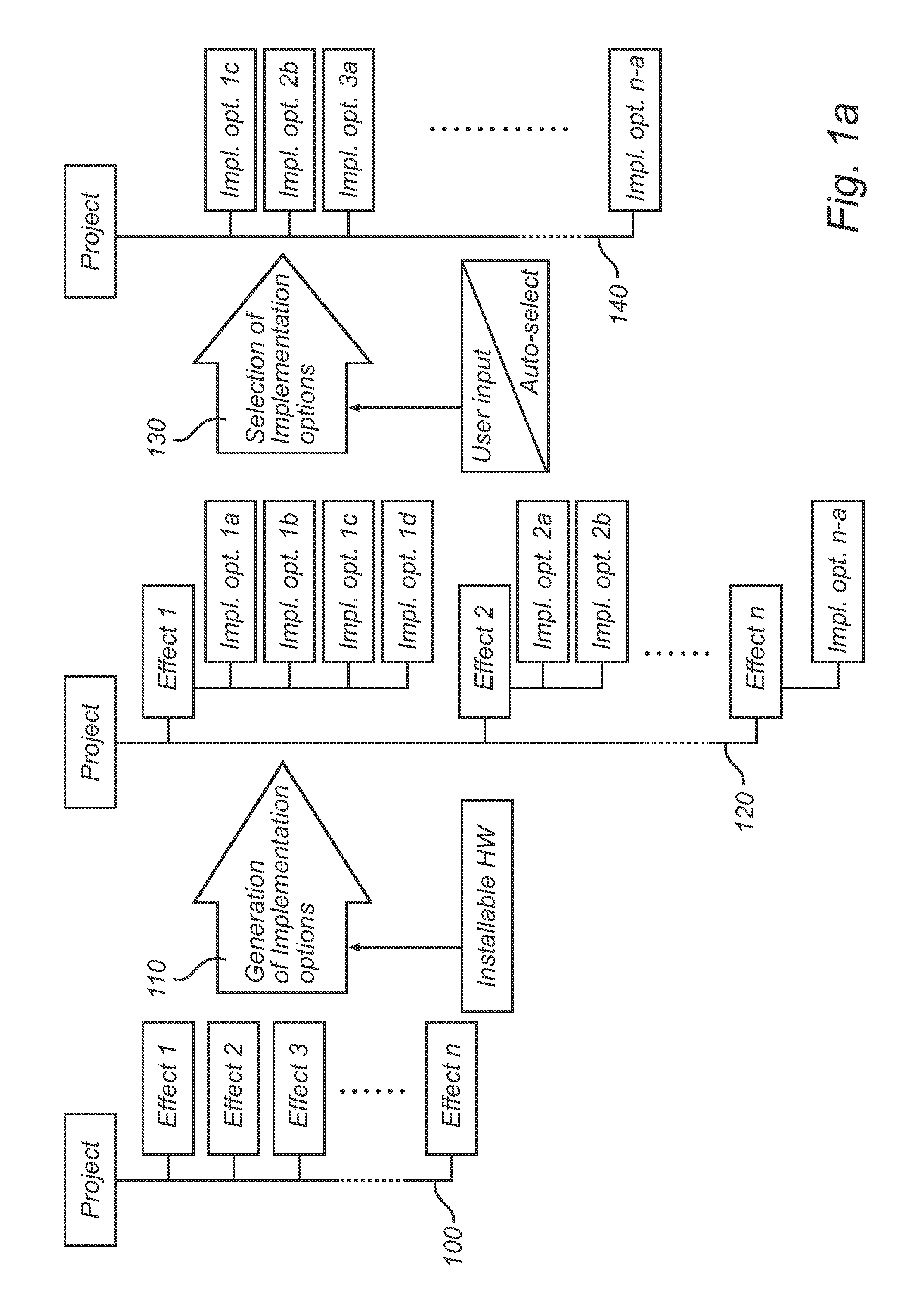
[0039]FIG. 1 illustrates an exemplary embodiment of the invention as a computer-implemented method for simulating realization of lighting effects in an environment. A set of n lighting effects, which are to be realized by selecting, acquiring, installing, programming and operating devices, will be referred to as a project in all stages of the realization process. The project is represented as a first tree 100 in a graphical user interface of a computer system carrying out the method. The leaves of the tree 100 represent the lighting effects entered by the user, which are labeled Effect 1, Effect 2, etc. The lighting effects may be entered by selection from a palette of effects in a graphical user interface, as will be further discussed below with reference to FIG. 6.

[0040]In a first processing step 110, implementation options are generated to realize the lighting effects. This generation of implementation options is based on data indicative of installable hardware devices. An implem...


PUM


Abstract

A method and a device for simulating the realization of lighting effects in an environment are disclosed. The method may receive environment data, user input indicative of lighting effects, and data indicative of what installable devices exist. Based thereon, the method may generate at least one implementation option for each lighting effect and select one implementation option for each lighting effect. As a result, realization data based on the environment data and selected implementation options options can be generated. A simulator for simulating realization of lighting effects is adapted to communicate, on the one hand, with a user or other provider of environment and lighting effect data, and, on the other, with a source of information on installable hardware device. The simulator can be operable in a design mode, an implementation mode, a selection mode and a realization mode.

Description

TECHNICAL FIELD[0001]The present invention generally relates to the area of design tools, particularly for lighting design. More precisely, it relates to a computer-implemented method for simulating the process of realizing lighting effects in an environment. As such, the realization process may include acquiring, installing and programming devices selected from a collection of available devices in accordance with generic design requirements.BACKGROUND[0002]Many existing tools for computer-aided lighting design are organized essentially as device palettes, from which the user can browse and select lighting devices (luminaries) to be purchased / rented and arranged in an environment. This is how Dialux™, a software tool developed by DIAL GmbH, is organized. Not uncommonly, the palette is populated with the product range currently available from a specific lighting device supplier. Such a device-oriented design interface forces the user into thinking in terms of existing devices and the...

Claims


Application Information

Patent Timeline
Patent Type & Authority Applications(United States)
IPC IPC(8): G06F17/50
CPCH05B37/029H05B47/155G06F30/20
Inventor LE GUEVEL-SCHOLTENS, ANTONIA GEBINAVAN DOORN, MARKUS GERARDUS LEONARDUSGALJAARD, SALOME
Owner SIGNIFY HLDG BV
Why Eureka
Try Eureka