[0008] According to one aspect, there is provided a
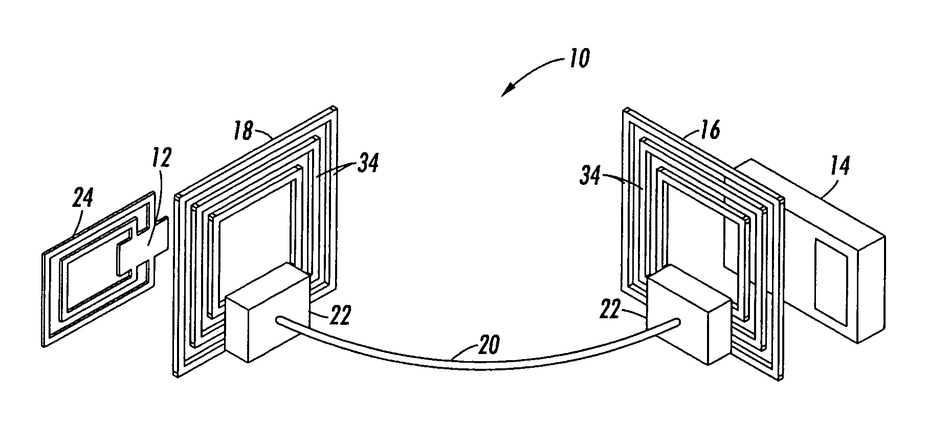
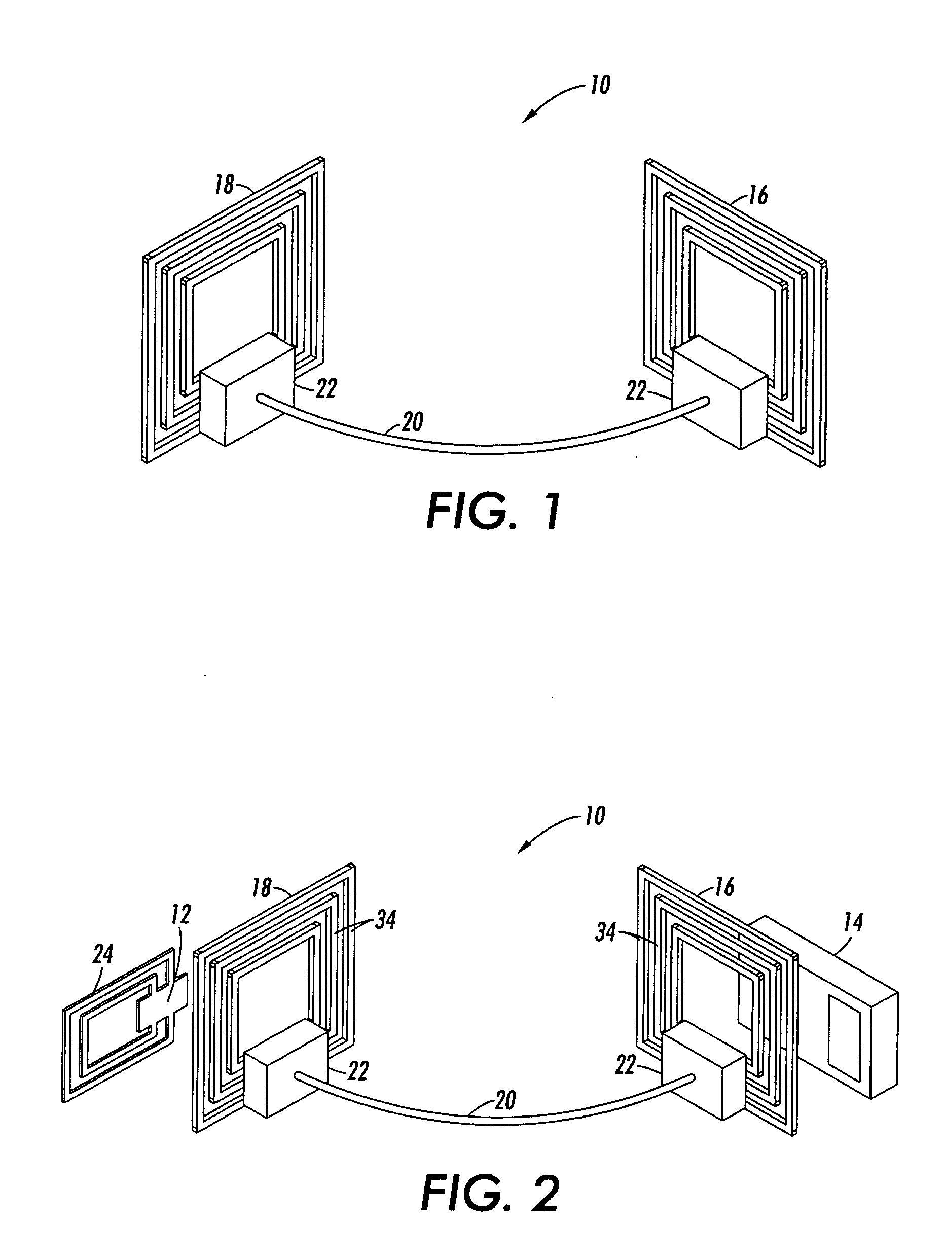
radio frequency identification (RFID) bridge antenna for increasing a distance over which a tag can communicate with a reader or coupler. Basically, the bridge antenna comprises at least two
radio frequency (RF) antenna elements spaced apart from one another and coupled together by an
electrical conductor. The first of the two RF elements is located
proximate to the reader antenna and the second RF element is located proximate to the tag antenna. An electromagnetic
carrier signal generated by the reader is transmitted to the first RF antenna element and is then passed through the conductor to the second RF element, bridging the gap between the tag and reader antennas and increasing the distance over which the tag can communicate with the reader.
[0009] In another aspect, there is provided a machine, such as a printing apparatus, containing at least one customer replaceable module or CRU, such as a
printing ink cartridge or toner
bottle, the module having a CRUM or tag associated therewith for wirelessly communicating data with a reader. The machine includes a RFID bridge antenna for extending the distance over which the tag can communicate with the reader. The bridge antenna includes a local RF antenna element positioned proximate to the reader antenna and a remote RF antenna element positioned proximate to the tag antenna. The two RF antenna elements are coupled together by a conductor of sufficient length to bridge the gap between the tag and reader antennas and thus enable communication between both the tag and reader over a distance that would otherwise not be possible.
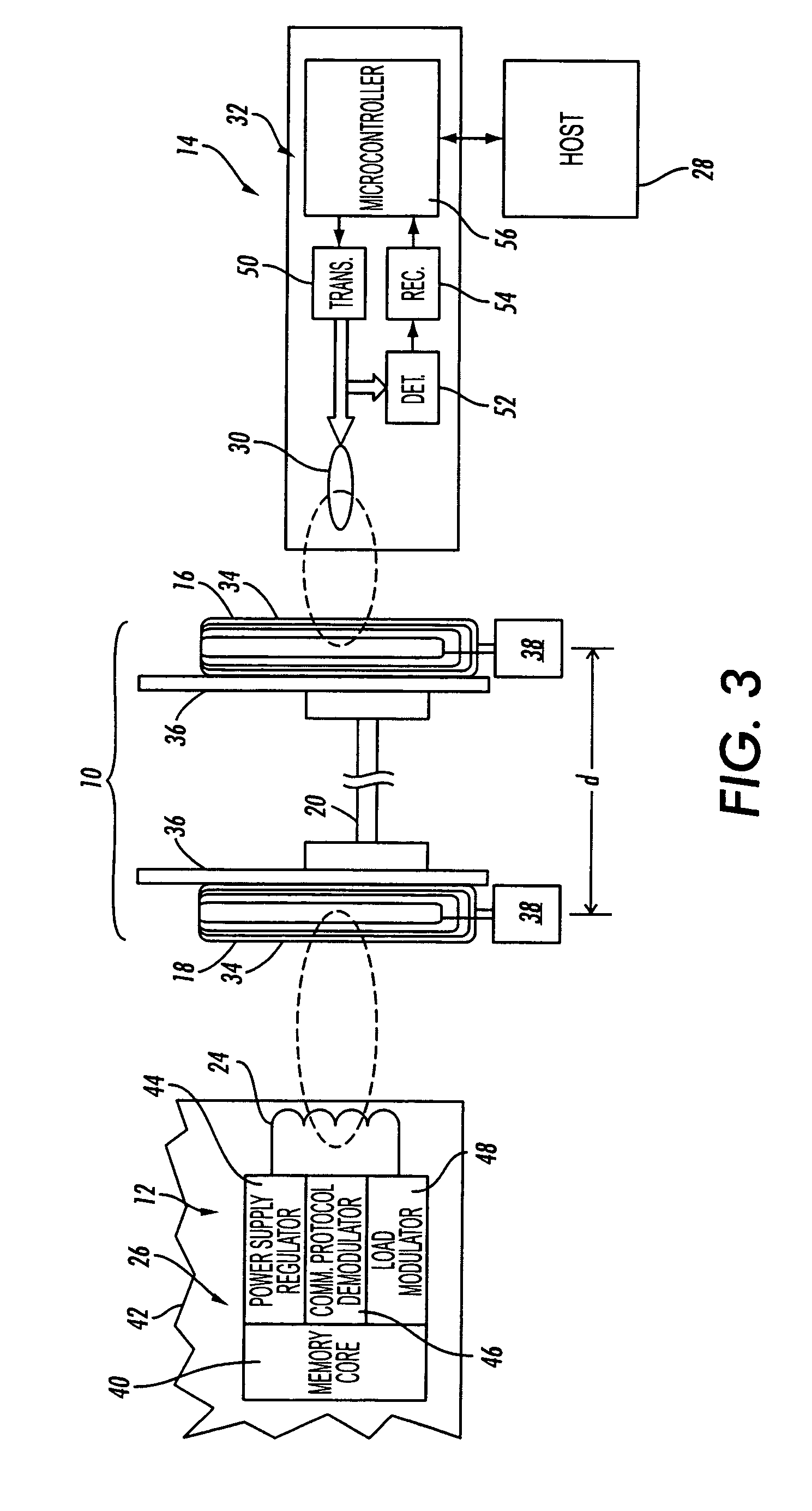
[0010] In another aspect, there is provided a package for storing an object having a tag associated therewith for wirelessly communicating data with a reader, wherein the object is placed in a remote location inside the package. An RFID bridge antenna is positioned inside the packaged for extending the distance over which the tag can communicate with the reader. The bridge antenna comprises a local RF antenna coil positioned proximate to the reader antenna and a remote RF coil positioned proximate to the tag antenna. An electromagnetic
carrier signal generated by the reader is transmitted by the reader antenna to the local RF coil, this
signal being then carried by an
electrical conductor to the remote RF antenna coil proximate to the tag antenna. The
signal is then retransmitted via the tag antenna to the tag, covering an overall distance which is significantly greater than would ordinarily be possible without the bridge antenna. Although the electrical conductor can be a simple open wire lead, it is preferred that the two RF antenna elements be electromagnetically coupled together using a flexible, low-loss, shielded co-axial cable or coax.
[0011] In another aspect, there is provided a package for storing multiple objects having a tag associated with more than one of the objects for wirelessly communicating data with a single reader, wherein at least one of the objects is remotely located inside the package. In this case, the reader is provided with at least one reader antenna arranged so as to transmit an electromagnetic carrier
signal to multiple tags associated with the objects. The tags communicate directly with the reader using a single RFID bridge antenna or a series of bridge antennas wirelessly communicating with a tag associated with at least one of the objects, the bridge antenna or antennas increasing the distance over which the tag or tags can communicate with the reader. The reader may be located either inside or outside of the package.
[0012] In still another aspect, there is provided a machine, such as a printing apparatus, including a case or cabinet having a hingeably mounted door providing access for storage of at least one
consumer replaceable module or CRU, such as a
bottle containing a printing material, (e.g. liquid ink), the
bottle having a CRUM or tag including a tag antenna associated therewith for wirelessly communicating data to a reader. The module or CRU is remotely located inside the case or cabinet and has its tag antenna in close proximity to the door when the door is closed. An RFID bridge antenna is mounted to the inner side of the door, such that when the door is closed, one of its two RF antenna coils is placed in close proximity to the container or bottle and its tag while the other RF coil is placed in close proximity to the reader also inside the case or cabinet. In this aspect, the bridge antenna utilizes the door as a co-planar, non-conductive substrate to increase the distance or gap over which the tag can communicate with a reader. Also, in this aspect, since both of the bridge antenna coils lie within the same plane on the inner side of the door, the antenna coils can be advantageously incorporated onto a single substrate such as a PC board, eliminating the need for a
flexible cable or coax such as may be required in order to make connection between antenna elements that may lie in different planes.
[0014] In yet another aspect, there is provided a method for increasing the distance over which a tag can communicate with a reader comprising providing a bridge antenna including at least two RF antenna elements, placing the two RF antenna elements in spaced apart relation, one in proximity to the reader and the other in proximity to the tag, providing an electrical conductor of sufficient length to extend across the gap between the tag and the reader and electrically connecting the two RF antenna elements together using the conductor, thereby increasing the distance over which the tag can communicate with the reader.

