
Method for mounting a piezoelectric resonator in a case and packaged piezoelectric resonator

Inactive Publication Date: 2012-04-26
MICRO CRYSTAL
View PDF2 Cites 25 Cited by
  • Summary
  • Abstract
  • Description
  • Claims
  • Application Information

AI Technical Summary

Benefits of technology

[0013]It is still a further object of the present invention to provide for bonding the piezoelectric resonator in the case without inducing significant thermal stress. Indeed, if the amount of thermal stress can be reduced, the size of the decoupling zone between the connection pads and the vibrating arms of the resonator can also be reduced in size. By reducing the size of the decoupling zone, it is possible to make packaged piezoelectric resonators with smaller overall dimensions; thus bringing miniaturization one step further.

Problems solved by technology

Indeed, as the dimensions of packaged piezoelectric resonators become smaller and smaller, the space in which the outgas can accumulate also becomes smaller and smaller.
In other words, the problem of outgasing becomes more and more critical as packaged piezoelectric resonators become smaller.

Method used


Image

  • Method for mounting a piezoelectric resonator in a case and packaged piezoelectric resonator
  • Method for mounting a piezoelectric resonator in a case and packaged piezoelectric resonator
  • Method for mounting a piezoelectric resonator in a case and packaged piezoelectric resonator

Examples


Embodiment Construction

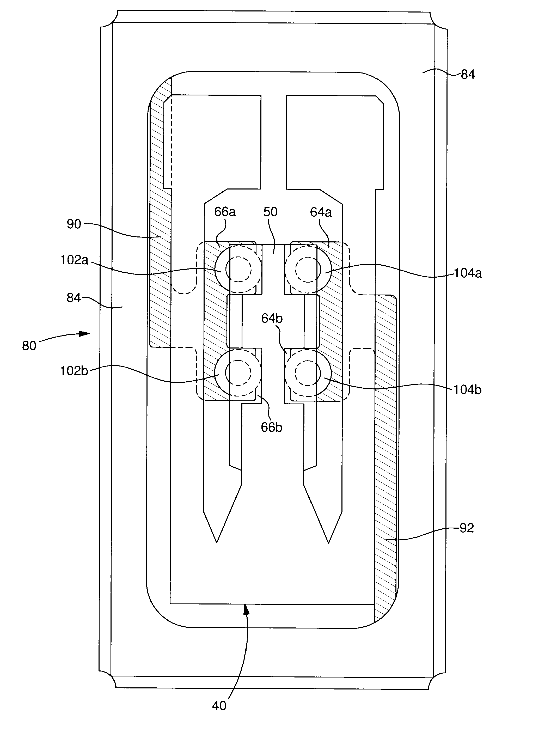
[0029]FIG. 3 shows a first embodiment of a piezoelectric resonator intended to be assembled with a case (not shown) in order to provide a packaged piezoelectric resonator according to the invention. The resonator designated by the reference numeral 40, includes a tuning fork shaped part with two vibrating arms 44 and 46 joined by a linking part 48 to which a central arm 50, located between arms 44 and 46 and parallel thereto, is attached. The whole resonator is in a single piece, preferably made from quartz. The vibrating arms 44 and 46 carry two groups of electrodes 56, 58. The electrodes in one group are connected to each other by conductive paths, respectively 60 and 62, carried by linking part 48. As they are shown in the drawing, the electrodes and conductive paths are arranged so as to make arms 44 and 46 vibrate in flexure mode as indicated by double arrows 38. However, they could have a different configuration to make the arms vibrate in the same mode or another mode (torsio...


PUM

PropertyMeasurementUnit
Distanceaaaaaaaaaa

Abstract

The invention concerns a method for mounting a piezoelectric resonator (40) inside a case (80) by ultrasonic bonding of the piezoelectric resonator to a base part of the case. The invention also concerns a small-sized packaged piezoelectric resonator, in which the piezoelectric resonator is ultrasonically bonded inside a base part of the package.

Description

FIELD OF THE INVENTION[0001]The present invention concerns a method for mounting a piezoelectric resonator inside a case by bonding the piezoelectric resonator to a base part of the case. The present invention also concerns a small-sized packaged piezoelectric resonator, in which the piezoelectric resonator is bonded inside a base part of the package and which is most often used for making frequency generators in particular for portable electronic equipment, in numerous fields such as horology, information technology, telecommunications and the medical field.BACKGROUND OF THE INVENTION[0002]Piezoelectric resonators are extensively used as a clock source for electronic circuits in a variety of electronic appliances. As electronic integrated circuits get smaller and smaller, attempts are continuously made to produce smaller and smaller resonators.[0003]In general Surface Mounting Device (SMD) type piezoelectric resonators may include a piezoelectric resonator piece mounted in a packag...

Claims


Application Information

Patent Timeline
IPC IPC(8): H01L41/053B32B37/00
CPCH03H9/0523H03H9/215H03H9/1021
Inventor DALLA PIAZZA, SILVIOLUETHI, THOMASSALLAZ, GUENTERBORLOZ, STEPHANE
Owner MICRO CRYSTAL
Learn More