Liquid crystal display module

Active Publication Date: 2012-04-26
AU OPTRONICS CORP
View PDF4 Cites 10 Cited by
  • Summary
  • Abstract
  • Description
  • Claims
  • Application Information

AI Technical Summary

Benefits of technology

[0010]The invention is directed to an LCD module in which the device arrangement is rather conducive to miniaturization of the LC

Problems solved by technology

However, under said arrangement, the FPC connected to the PCB and the LCD panel needs to detour around the back bezel and the backlight module located on the back bezel, which leads to an increase in the required length of the FPC and the material costs of the FPC.
Thereby, the FPC is more likely to be damaged.
Nonetheless, the PCB is configured at the side of the backlight mo

Method used


Image

  • Liquid crystal display module
  • Liquid crystal display module
  • Liquid crystal display module

Examples


Embodiment Construction

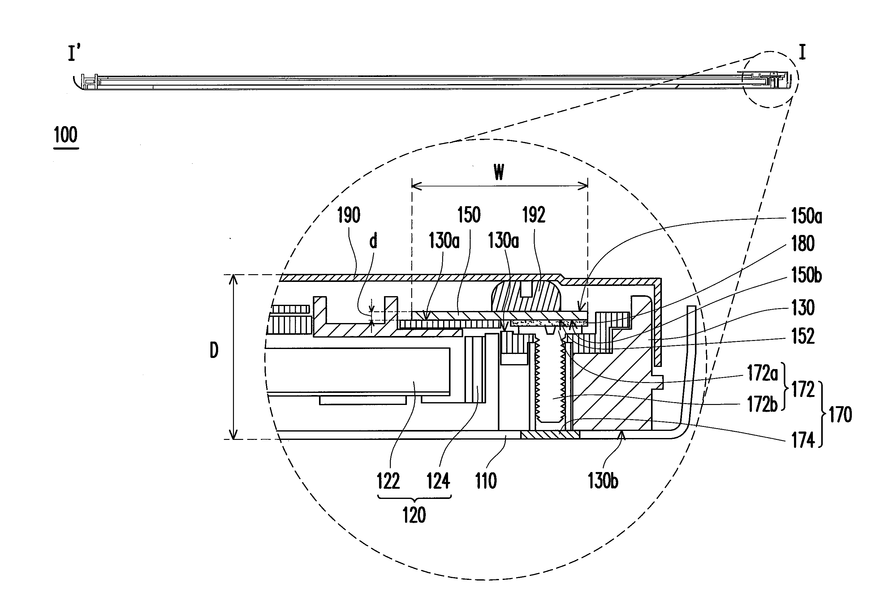
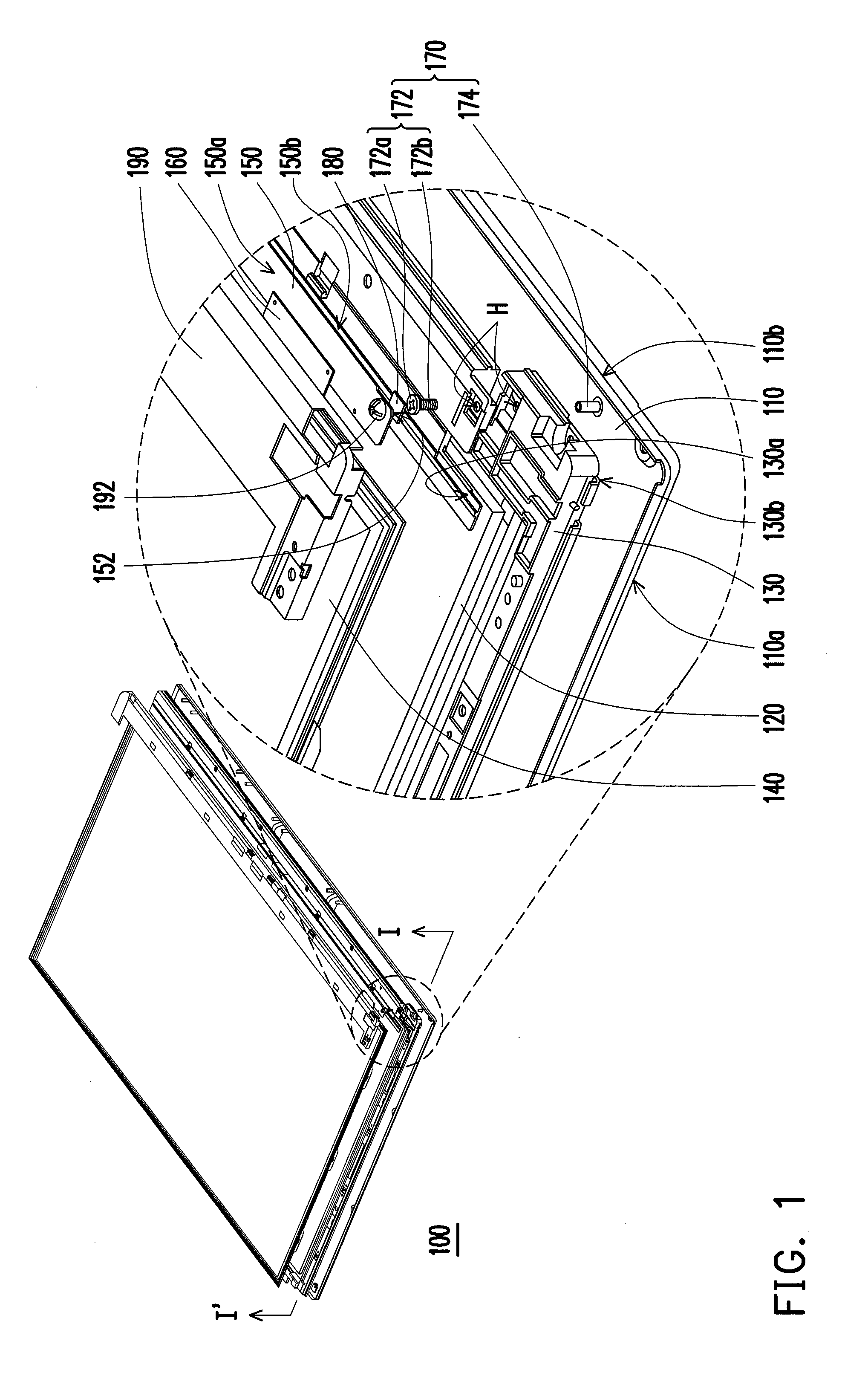
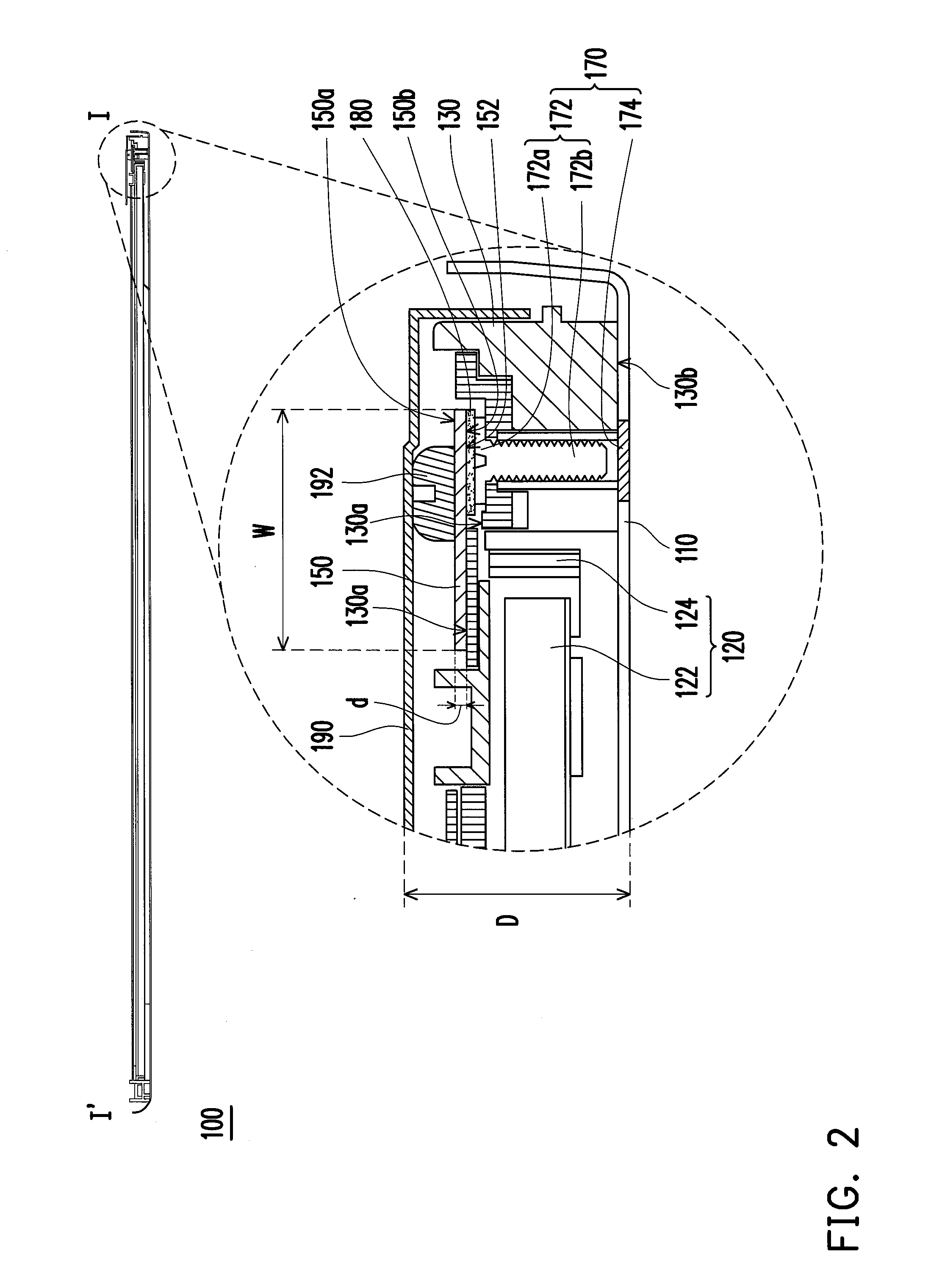
[0018]FIG. 1 is a three-dimensional exploded view illustrating an LCD module 100 according to an embodiment of the invention. FIG. 2 is a schematic cross-sectional view illustrating the LCD module 100 taken alone a sectional line I-I′ depicted in FIG. 1. With reference to FIG. 1 and FIG. 2, the LCD module 100 of this embodiment includes a back bezel 110, a backlight module 120, a frame 130, an LCD panel 140, a circuit board 150, an assembling element 170, and a gasket 180.

[0019]The back bezel 110 mainly carries and protects the elements configured thereon. Here, the back bezel 110 is preferably made of materials with favorable mechanical properties, high thermal conductivity, and great electrical conductivity, such as stainless steel, tinplate, or other appropriate materials.

[0020]The backlight module 120 is configured on the back bezel 110. In this embodiment, the backlight module 120 can include a light guide plate (LGP) 122 and a light emitting device 124, as shown in FIG. 2. It ...


PUM


Abstract

A liquid crystal display (LCD) module includes a back bezel, a backlight module, a frame, an LCD panel, a circuit board, an assembling element, and a gasket. The frame has a top part and a bottom part opposite to the top part, and the bottom part faces the back bezel. The circuit board is configured on the top part of the frame and has a first surface and a second surface opposite to the first surface. The second surface faces the frame, and the circuit board has a ground area on the second surface. The assembling element pierces through the frame and connects the frame to the back bezel. The gasket leans against the ground area of the circuit board and the assembling element to form a conductive path from the ground area, the gasket, the assembling element to the back bezel.

Description

CROSS-REFERENCE TO RELATED APPLICATION[0001]This application claims the priority benefit of Taiwan application serial no. 99136352, filed on Oct. 25, 2010. The entirety of the above-mentioned patent application is hereby incorporated by reference herein and made a part of this specification.BACKGROUND OF THE INVENTION[0002]1. Field of the Invention[0003]The invention relates to a liquid crystal display (LCD) module. More particularly, the invention relates to an LCD module that can be easily miniaturized.[0004]2. Description of Related Art[0005]A conventional LCD module includes a backlight module located on a surface of a back bezel, an LCD panel located on the backlight module, a flexible printed circuit (FPC) connected to the LCD panel, and a printed circuit board (PCB) connected to the FPC.[0006]To prevent electromagnetic interference (EMI), the PCB is often electrically connected to the back bezel, such that the PCB is grounded to prevent the EMI.[0007]According to the related ...

Claims


Application Information

Patent Timeline
IPC IPC(8): G02F1/1333
CPCG02F1/133308G02F2001/133334G02F2001/133314G02F1/13452G02F1/133314G02F1/133334
Inventor LIN, YUE-FENGCHUANG, TSUNG-HSIENCHENG, TSUNG-FUSHEN, CHANG-HO
Owner AU OPTRONICS CORP
Why Eureka
Try Eureka