Retroreflective lenticular arrays

a technology of lenticular arrays and lenticular arrays, which is applied in the field of retroreflective lenticular arrays, can solve the problems of adding installation and operating costs, static and only capable of displaying signs, and lack of dynamic effects such as flashing or a rapid succession of different patterns or images, so as to enhance the conspicuity and visibility of the device, enhance the brightness, and enhance the visual brightness

Active Publication Date: 2012-04-26
S V V TECH INNOVATIONS
View PDF9 Cites 47 Cited by
  • Summary
  • Abstract
  • Description
  • Claims
  • Application Information

AI Technical Summary

Benefits of technology

[0015]Each of the retroreflective areas can have one or more retroreflectors, such as cube-corners, glass spheres or right-angle prisms which reflect the light essentially into the same direction as the direction of the incidence. The retroreflectors reflect back a substantial portion of light entering the focusing array thus enhancing the visual brightness. Furthermore, as the approaching vehicle changes the illumination and viewing angle relatively to the retroreflective lenticular system, the retroreflective areas and the separation areas are exposed to the driver's view in succession, thus providing substantial changes in the apparent brightness of the system or it portions. By defining different patterns of by suitable interlacing of retroreflective areas and separation areas, various visual effects can be obtained in enhanced brightness, such as flashing, flip, animation, and the like.
[0016]The retroreflective lenticular system can have one or more dynamic effect areas in which the individual focusing elements of the focusing array are preferably arranged relative to the retroreflective areas and the separation areas so that a substantial portion of incident light is focused or superimposed on either the retroreflective areas or the separation areas, resulting in varying cumulative retroreflection from the dynamic effect areas. By suitable interlacing of the retroreflective areas and the separation areas in accordance with the pitch of the focusing elements in the focusing array, the entire dynamic area can be made variable in brightness and / or color. In addition, various patterns, symbols and image content can be encoded by the interlaced retroreflective and separation areas so that multiple image frames can be displayed in succession and in varying brightness levels, thus enhancing the conspicuity and visibility of the device incorporating the retroreflective lenticular system of the present invention.

Problems solved by technology

The conventional signs, however, are static and only capable of displaying only a single pattern or image that can be seen by the driver, and usually only in one color.
While these conventional solutions improve the apparent brightness of the signs, they lack any dynamic effects such as flashing or a rapid succession of different patterns or images.
However, the active light sources require constant energy supply which adds to the installation and operating costs.
The energy requirement is especially problematic in remote areas with no power lines and where the maintenance and energy supply can be limited.
However, the conventional lenticular screens are usually only capable of displaying the images that are printed in the back of the lens array and their ability to catch observer's eye is usually limited to changing the image content and colors only.
The image prints are scattering light into all directions thus resulting in a much poorer visibility from a distance compared to the state-of-the art signs and markings having retroreflective capabilities.
Therefore, the conventional lenticuar screens are ill suited for improving the visibility of road signs or for similar sign and display applications.

Method used


Image

  • Retroreflective lenticular arrays
  • Retroreflective lenticular arrays
  • Retroreflective lenticular arrays

Examples


Embodiment Construction

[0057]Referring more specifically to the drawings, for illustrative purposes the present invention is embodied in the apparatus generally shown in the preceding figures. It will be appreciated that the apparatus may vary as to configuration and as to details of the parts without departing from the basic concepts as disclosed herein. Furthermore, elements represented in one embodiment as taught herein are applicable without limitation to other embodiments taught herein, and in combination with those embodiments and what is known in the art.

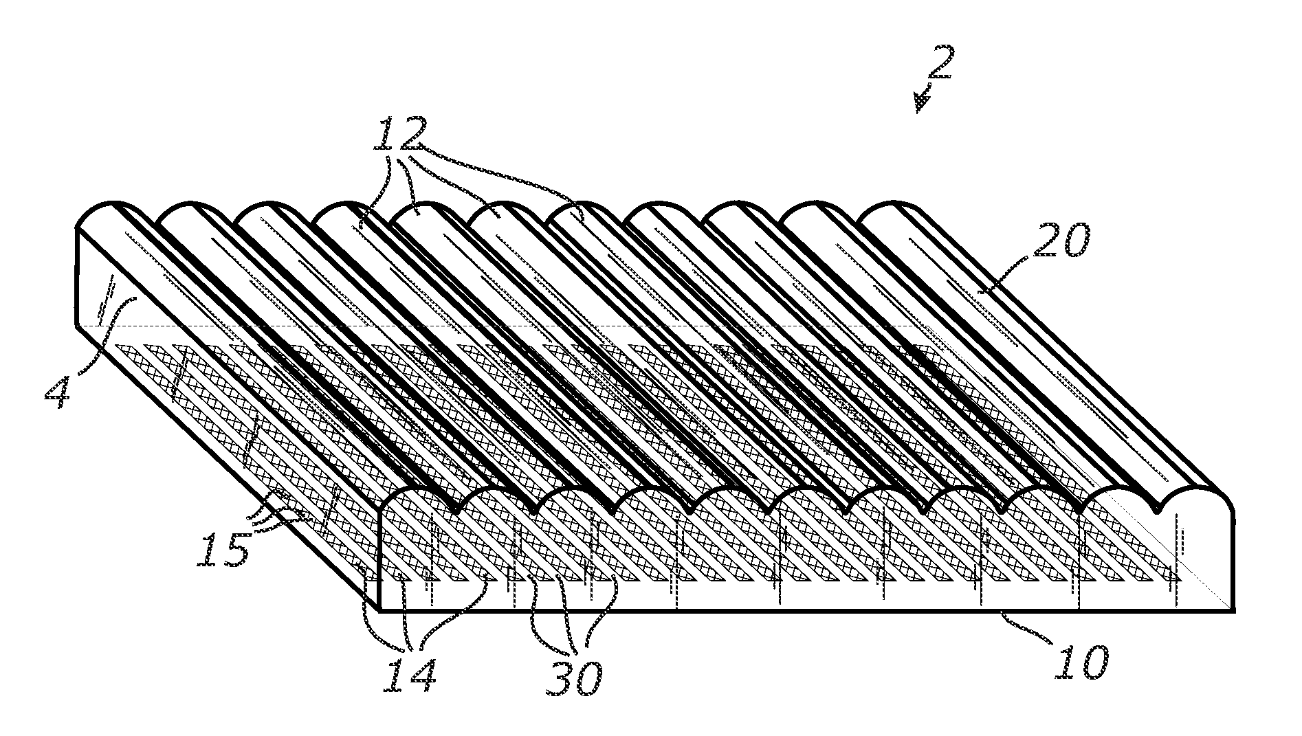
[0058]According to a preferred embodiment of the present invention, a retroreflective lenticular system is provided that can provide flashing effects or display multiple patterns, symbols or image contents in succession and in variable brightness and / or can provide various attention-catching effects such as flip or animation when being illuminated by the headlamps of an approaching vehicle.

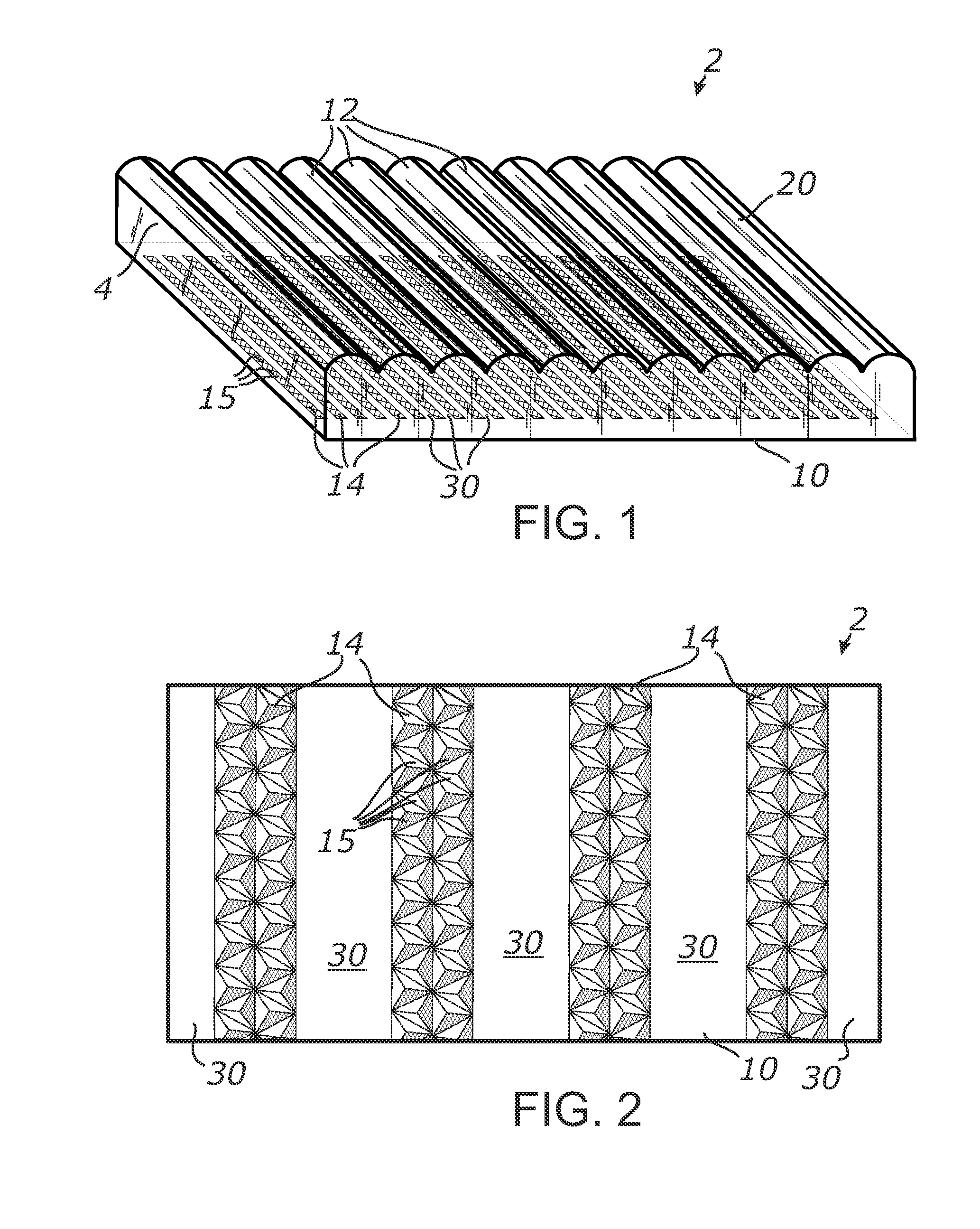
[0059]FIG. 1 illustrates an embodiment of a retroreflective...


PUM

PropertyMeasurementUnit
widthaaaaaaaaaa
widthaaaaaaaaaa
widthaaaaaaaaaa

Abstract

Retroreflective lenticular systems employing a focusing array and a retroreflector array optically coupled to the focusing array. The focusing array is provided on a first surface and the retroreflector array is provided on an opposing second surface. The retroreflector array includes an array of retroreflective elements alternating with separation areas and disposed in energy exchange relationship with respect to the focusing array. The focusing array includes a plurality of focusing lenses configured to illuminate only the retroreflective elements with focused beams at least at some angles and to focus the incident beam only onto the separation areas at other angles. The intermittent illumination of retroreflective elements provides variable retroreflectivity of at least portions of the system and enhances the system visibility and conspicuity in the reflected light.

Description

CROSS-REFERENCE TO RELATED APPLICATIONS[0001]This application claims priority from U.S. provisional application Ser. No. 61 / 455,578 filed on Oct. 22, 2010, incorporated herein by reference in its entirety.STATEMENT REGARDING FEDERALLY SPONSORED RESEARCH OR DEVELOPMENT[0002]Not ApplicableINCORPORATION-BY-REFERENCE OF MATERIAL SUBMITTED ON A COMPACT DISC[0003]Not ApplicableNOTICE OF MATERIAL SUBJECT TO COPYRIGHT PROTECTION[0004]A portion of the material in this patent document is subject to copyright protection under the copyright laws of the United States and of other countries. The owner of the copyright rights has no objection to the facsimile reproduction by anyone of the patent document or the patent disclosure, as it appears in the United States Patent and Trademark Office publicly available file or records, but otherwise reserves all copyright rights whatsoever. The copyright owner does not hereby waive any of its rights to have this patent document maintained in secrecy, inclu...

Claims


Application Information

Patent Timeline
Patent Type & Authority Applications(United States)
IPC IPC(8): G02B5/124B32B37/00B29D11/00
CPCB29D11/00278B29D11/00605Y10T156/10G02B5/12G02B5/124
Inventor VASYLYEV, SERGIY VICTOROVICH
Owner S V V TECH INNOVATIONS
Why Eureka
Try Eureka