Dynamic line management

a technology of dynamic line management and subscriber line, applied in the field of dynamic line management, can solve the problems of not being found out about and acted upon time critical information, and achieve the effects of reducing the snr margin, increasing the headline bit rate, and improving latency

Active Publication Date: 2012-04-26
BRITISH TELECOMM PLC
View PDF2 Cites 11 Cited by
  • Summary
  • Abstract
  • Description
  • Claims
  • Application Information

AI Technical Summary

Benefits of technology

[0021]It will thus be appreciated, that the lower the SNR Margin, the higher the headline bit rate that will be achievable (i.e. assuming that there are no errors). Likewise, the higher the SNR Margin, the more likely that the connection will operate in a stable manner, even in a fluctuating noise environment.
[0022]Fast/interleave mode switches the depth of interleave between no interleave (FAST mode) and any of the depths of interleave defined in the currently applicable ADSL standards (e.g. the ITU G.992.x standards). In many implementations, only the lowest level of interleave (a depth of 2, where units in a single code word which are adjacent before interleaving are separated by one interleaved unit from another word after interleaving) is used at the moment; however, this can change in the future. As is well known in the art, use of interleave protec...

Problems solved by technology

This resulted in time critical information not being found out ...

Method used


Image

  • Dynamic line management
  • Dynamic line management
  • Dynamic line management

Examples


Embodiment Construction

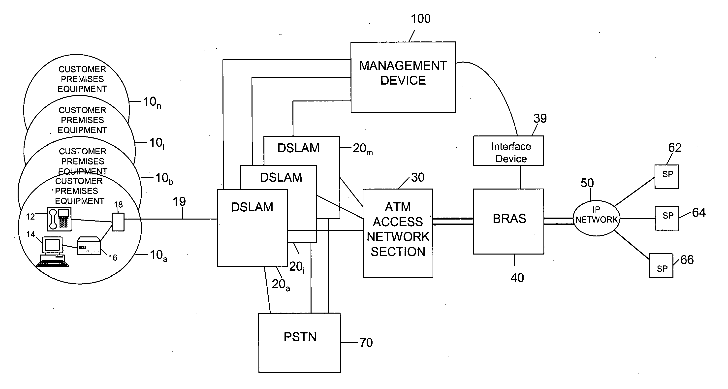
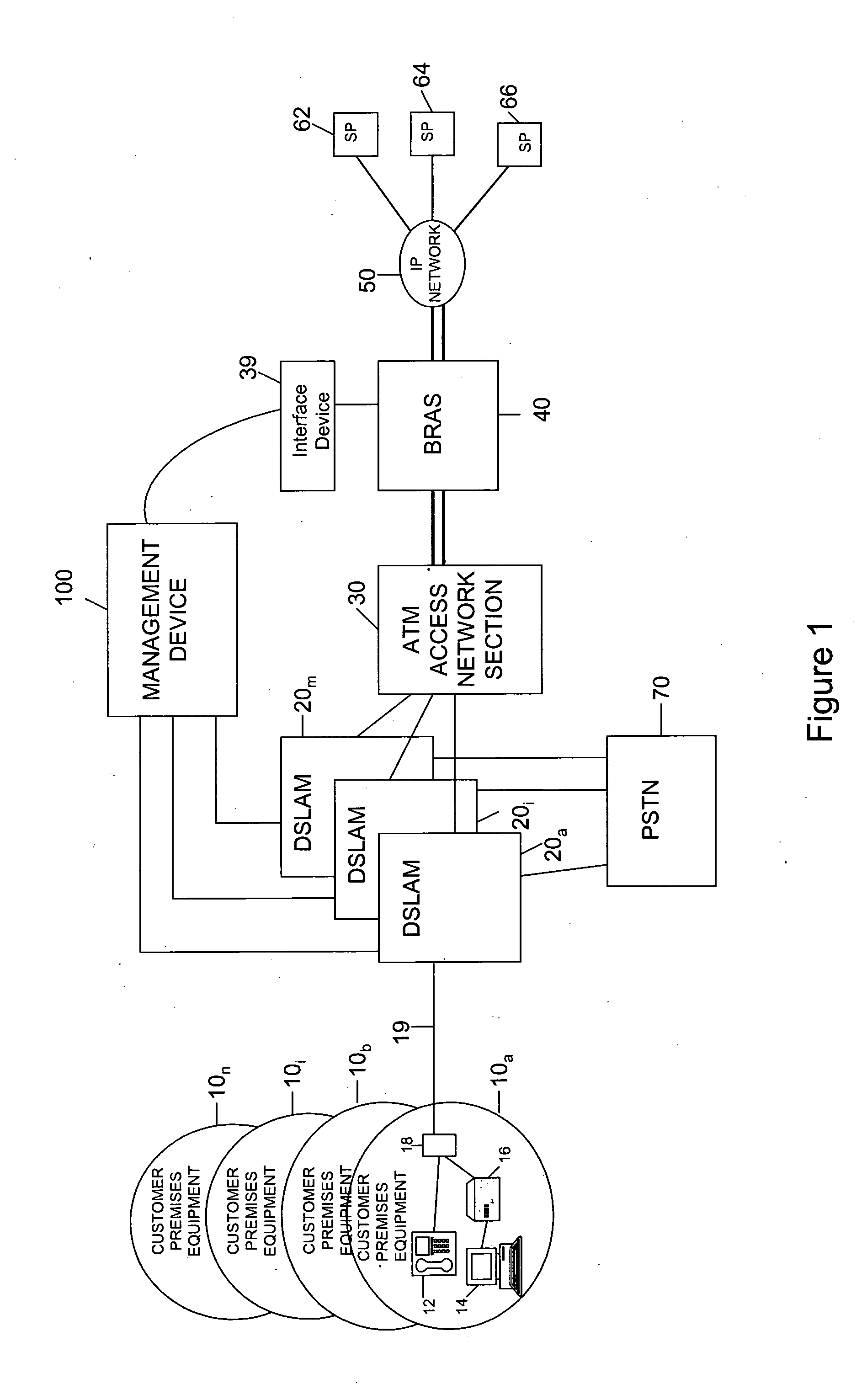
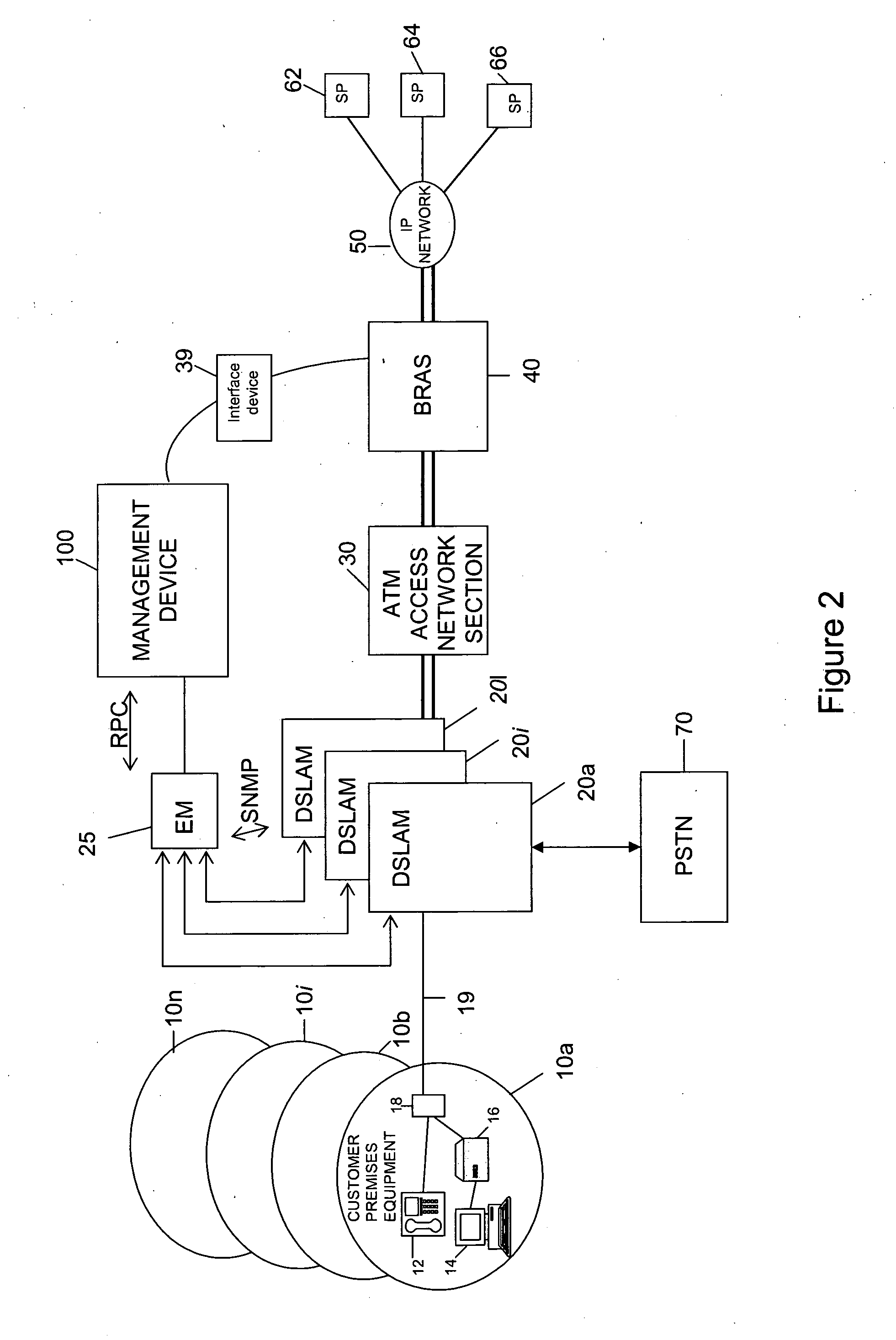
[0030]Referring to FIG. 1, an embodiment is illustrated in overview. Copper pair loops 19 connect a number of sets of customer premises equipment 10a, 10b . . . 10i . . . 10n to a smaller number of DSLAMs 20a . . . 20i . . . 20l. Each DSLAM is typically located within a local exchange (also known as a central office in the US) each of which can house one or more DSLAMs. Each DSLAM 20 separates normal voice traffic and data traffic and sends the voice traffic to the Public Switched Telephone Network (PSTN) 70. The data traffic is passed on through a core Access Network section 30 (which will typically be an ATM network section as is assumed in this embodiment) to a Broadband Remote Access Server (BRAS) 40 at which several IP traffic flows from (and to) multiple Service Providers (SP's) 62, 64, 66 are aggregated (and disaggregated) via an IP network 50 (which can itself be provided on top of an ATM network). Note that although only a single BRAS is shown, in practice a large access ne...


PUM


Abstract

A Digital Subscriber Line Access Multiplexor (DSLAM) for operation within an access network includes a plurality of digital subscriber line modems for terminating a plurality of corresponding digital subscriber lines and aggregating them for onward connection through the access network. The DSLAM is operable, each time a data connection is established or re-established over one of the digital subscriber lines, to generate line data about the data connection at the DSLAM, to store the line data, to wait a predetermined period of time, to determine if the data connection is still operating successfully since the establishment of the connection without having suffered loss of connection during the predetermined period and then to transmit the line data to a management device 100 which performs dynamic line management based on the data.

Description

RELATED APPLICATIONS[0001]The present application is a National Phase entry of PCT Application No. PCT / GB2010 / 000504, filed Mar. 19, 2010, which claims priority from European Patent Application No. 09250968.6, filed Mar. 31, 2009, the disclosures of which are hereby incorporated by reference herein in their entireties.TECHNICAL FIELD[0002]The invention relates to the dynamic management of Digital Subscriber Line (DSL) connections, which is often referred to as Dynamic Line Management (DLM).BACKGROUND[0003]DSL connections enable large bandwidth connections to be established over legacy twisted copper pair connections originally designed to carry simple voice calls only. The techniques employed to achieve this are sophisticated and ensuring that the correct settings are used in the DSL modems at either end of the connection in order to achieve an optimum balance between throughput characteristics (e.g. bandwidth, delay, jitter, etc.) and reliability characteristics (e.g. number of err...

Claims


Application Information

Patent Timeline
IPC IPC(8): H04L12/26
CPCH04L12/2878H04L41/0654H04M3/304H04L43/0811H04L41/32
Inventor CROOT, CHRISTOPHER MARCUSPICKERING, ASHLEYLINNEY, TREVOR PHILIPEVERETT, PHILIP ANTONYCOOK, JOHN WOLSEY
Owner BRITISH TELECOMM PLC
Why Eureka
Try Eureka