Stringer

a composite material and stringer technology, applied in the field of laminated composite stringers, can solve the problems of panel and stringer a tendency to separate, stringer termination geometries do not fully exploit the benefits of constructing stringers from composite materials, and the area of local stress concentration, so as to reduce the thickness of the stack, increase the geometric possibilities of stringer termination, and inhibit crack initiation

Inactive Publication Date: 2012-04-26
AIRBUS OPERATIONS LTD
View PDF9 Cites 51 Cited by
  • Summary
  • Abstract
  • Description
  • Claims
  • Application Information

AI Technical Summary

Benefits of technology

[0012]By contrast with the prior art, where the stack thickness remains the same in the web taper, the stringer of the present invention has a taper of reducing stack thickness. This greatly increases the geometric possibilities for the stringer termination and allows load to be far more effectively transferred from the stringer into the panel. The load transition is controlled and evenly distributed in a free-flow form instead of having to manage local stress concentrations. For most loading scenarios, the load transition

Problems solved by technology

Stringer terminations therefore cause areas of local stress concentration and the panel and stringer have a tendency to separate in these

Method used


Image

  • Stringer
  • Stringer
  • Stringer

Examples


first embodiment

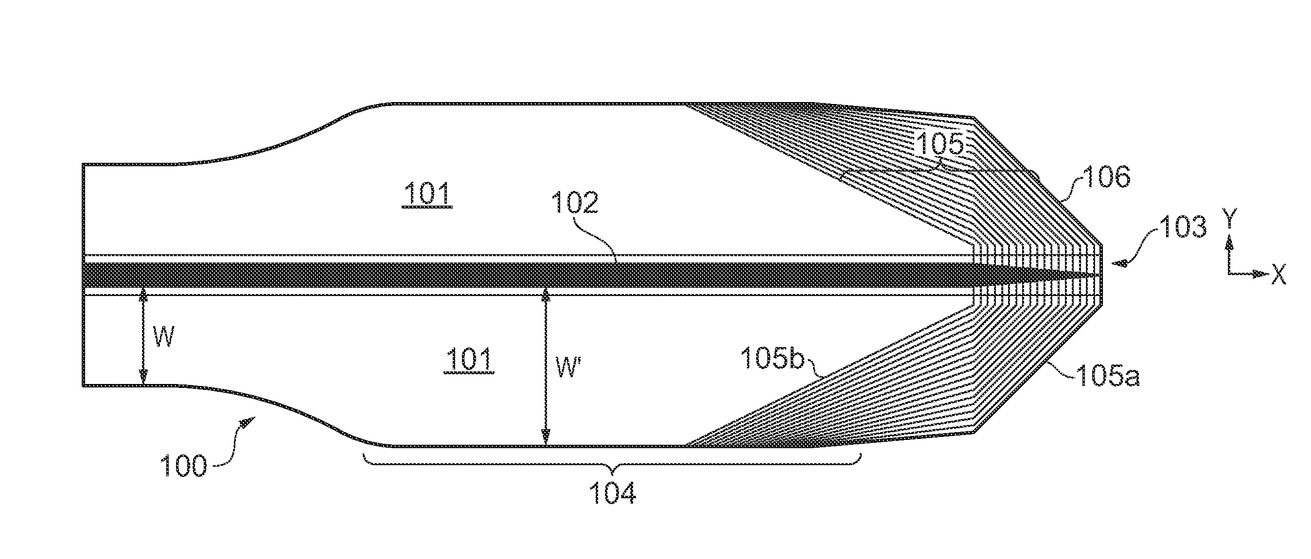
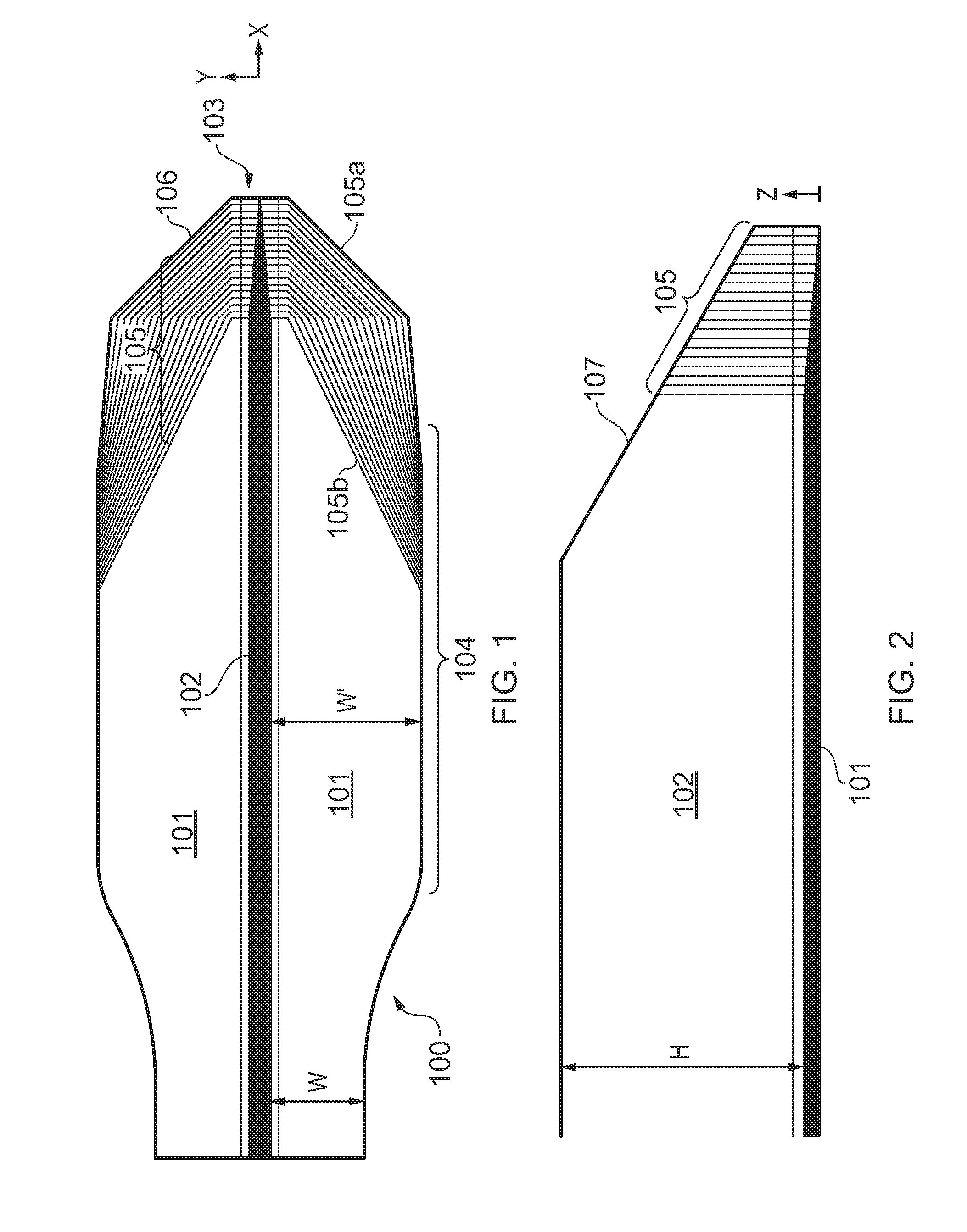
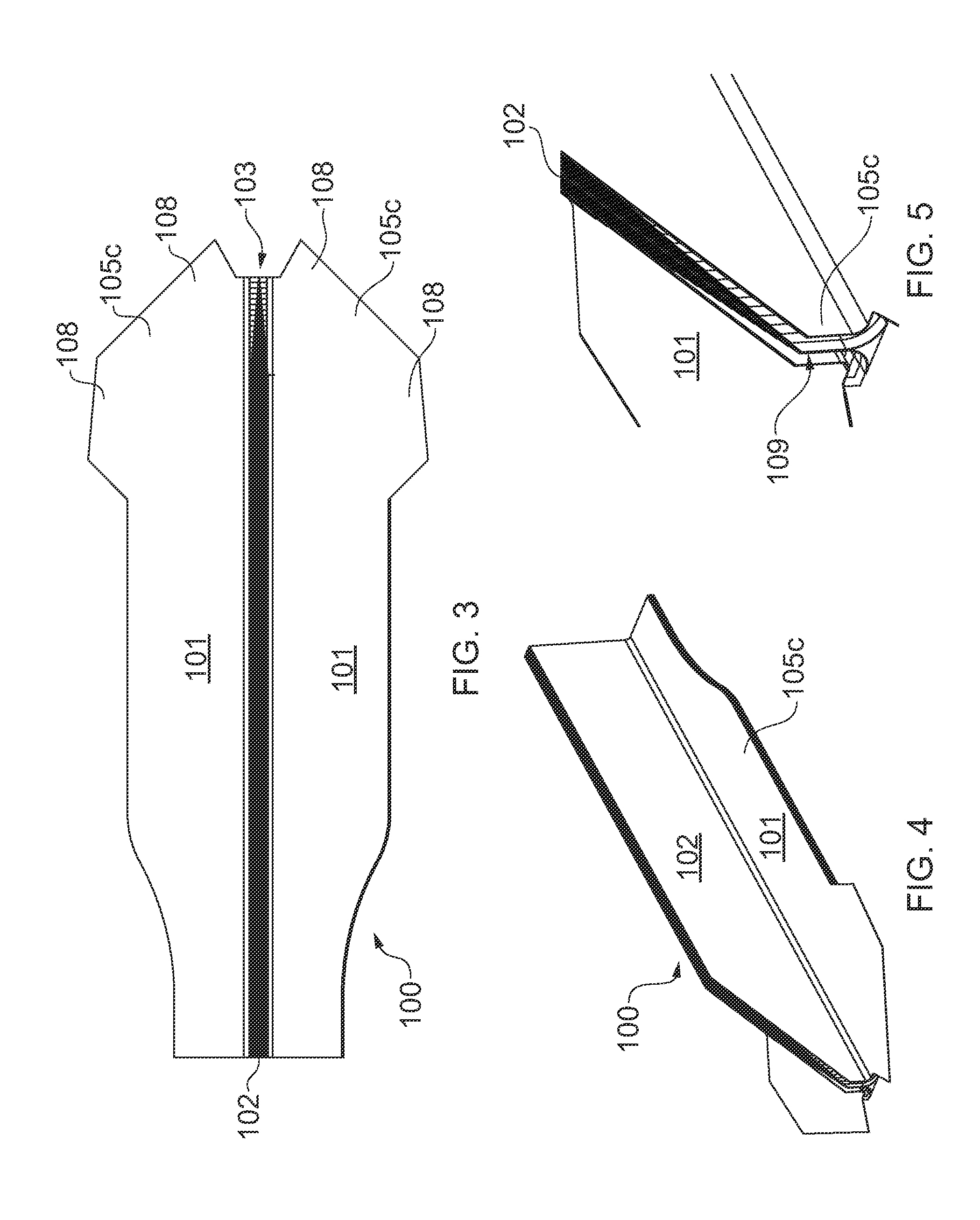
[0045]a stringer in accordance with the present invention will now be described. As shown in FIG. 1, the stringer 100 includes a flange 101 having a width W and an upstanding web 102 having a height H. Note that only one end of the stringer is shown in FIG. 1. The stringer 100 has a termination 103 at one end. Inboard of the termination, the stringer 100 has substantially constant section (not shown in FIG. 1). Adjacent to the termination 103, the flange 101 has a region of increased width W′ so as to form a stringer foot 104. The stringer 100 is formed from a pair of back-to-back L-shaped stacks of composite laminate plies 105.

[0046]The plies 105 are arranged such that the lowermost ply 105a is the largest ply and the uppermost ply 105b is the smallest ply. The plies are cut such that the lowermost ply 105a terminates at the stringer termination 103, and the uppermost ply 105b terminates a significant distance inboard of the termination 103. The remaining plies 105 intermediate the...

third embodiment

[0059]FIGS. 21 to 24 illustrate a stringer 300. The stringer 300 includes a stack of plies 305 arranged in a similar manner to those of the stringer 100. That is to say, the lowermost ply 305a is the largest ply and the uppermost ply 305b is the smallest ply. The stringer foot 304 has a free-form construction of substantially continuous curved edges, in contrast with the angular cut edges of the plies 105 of the stringer 100. The shape of the stringer foot 304 has been optimised for load transfer into a panel to which the stringer 300 is to be attached. However, the curved edges of the plies 305 are more difficult to cut than the straight edges of the plies 105 and 205 of the stringers 100 and 200, respectively.

[0060]To improve bonding of the stringer foot 304 to a panel 350 a pad 370 is laid over the stringer foot 304. The pad 370 effectively acts as a region of increased panel thickness for the panel 350. The pad 370 has a generally semi-circular or D-shaped construction of substa...


PUM

PropertyMeasurementUnit
Thicknessaaaaaaaaaa
Structureaaaaaaaaaa
Widthaaaaaaaaaa

Abstract

A laminated composite stringer having a termination at one end in its longitudinal direction, and including a laminated stack of composite structural plies, wherein internal plies in the stack are terminated consecutively towards the stringer termination to provide a taper of reducing stack thickness. Also, a composite structure comprising a panel and the stringer; and a method of manufacturing the stringer. The composite structure may be used in aircraft.

Description

FIELD OF THE INVENTION[0001]The present invention relates to a laminated composite stringer having a taper at its termination, and to a method of forming such a stringer.BACKGROUND OF THE INVENTION[0002]A panel, such as the skin of an aircraft wing or fuselage, may be reinforced by a series of elongate stringers which run along the length of the panel. The stringer typically comprises a web extending at right angles to the panel, and a flange engaging the panel.[0003]Stiffeners have to be terminated in certain areas due to obstructions so that the panel / stringer structure assumes a flat plate geometry. In the case of an aircraft, stiffeners have to be terminated at, e.g. the wing tips, access holes, etc. At the stringer termination, stress supported by the stringer is transferred into the panel. Stringer terminations therefore cause areas of local stress concentration and the panel and stringer have a tendency to separate in these areas.[0004]To improve resistance to separation of t...

Claims


Application Information

Patent Timeline
IPC IPC(8): B32B3/00B32B38/10
CPCB29C70/30B29D99/0014Y10T428/24479Y02T50/433Y10T156/1062B64C1/064Y02T50/40B29C70/302
Inventor BORGHINI-LILLI, MATTEOHADLEY, PAULPHILLIPS, NATHAN
Owner AIRBUS OPERATIONS LTD
Why Eureka
Try Eureka