
Improved abrasive saw

Inactive Publication Date: 2012-04-26
ILLINOIS TOOL WORKS INC
View PDF0 Cites 12 Cited by
  • Summary
  • Abstract
  • Description
  • Claims
  • Application Information

AI Technical Summary

Benefits of technology

[0016]The enclosure includes at least one wear element disposed on the inside of the enclosure, aligned with the direction of rotation of the associated cutting wheel, to prevent erosion of the enclosure.

Problems solved by technology

Among other things, this can result in too great of a force being exerted on the sample (and the blade) which can overheat the sample and blade.
This can also result in excessive stress on the saw motor.
In addition, such known saws are often belt driven, but do not have ready means for adjusting the belt to assure proper tension for blade drive.

Method used


Image

  • Improved abrasive saw
  • Improved abrasive saw
  • Improved abrasive saw

Examples


Embodiment Construction

[0036]While the present invention is susceptible of embodiment in various forms, there is shown in the drawings and will hereinafter be described a presently preferred embodiment with the understanding that the present disclosure is to be considered an exemplification of the invention and is not intended to limit the invention to the specific embodiment illustrated.

[0037]It should be further understood that the title of this section of this specification, namely, “Detailed Description Of The Invention”, relates to a requirement of the United States Patent Office, and does not imply, nor should be inferred to limit the subject matter disclosed herein.

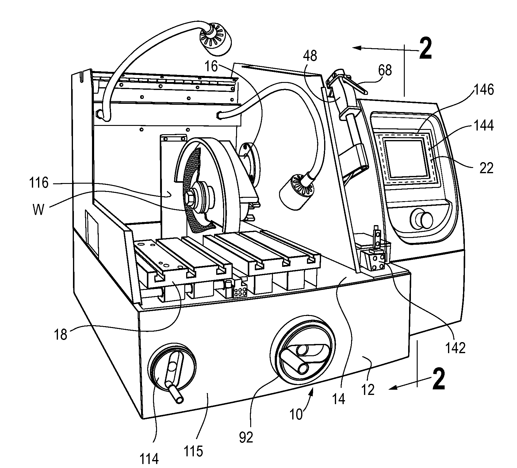
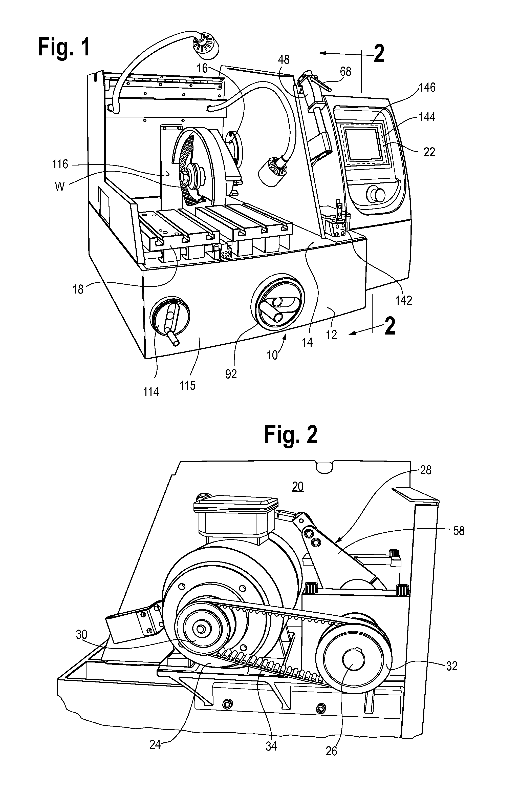
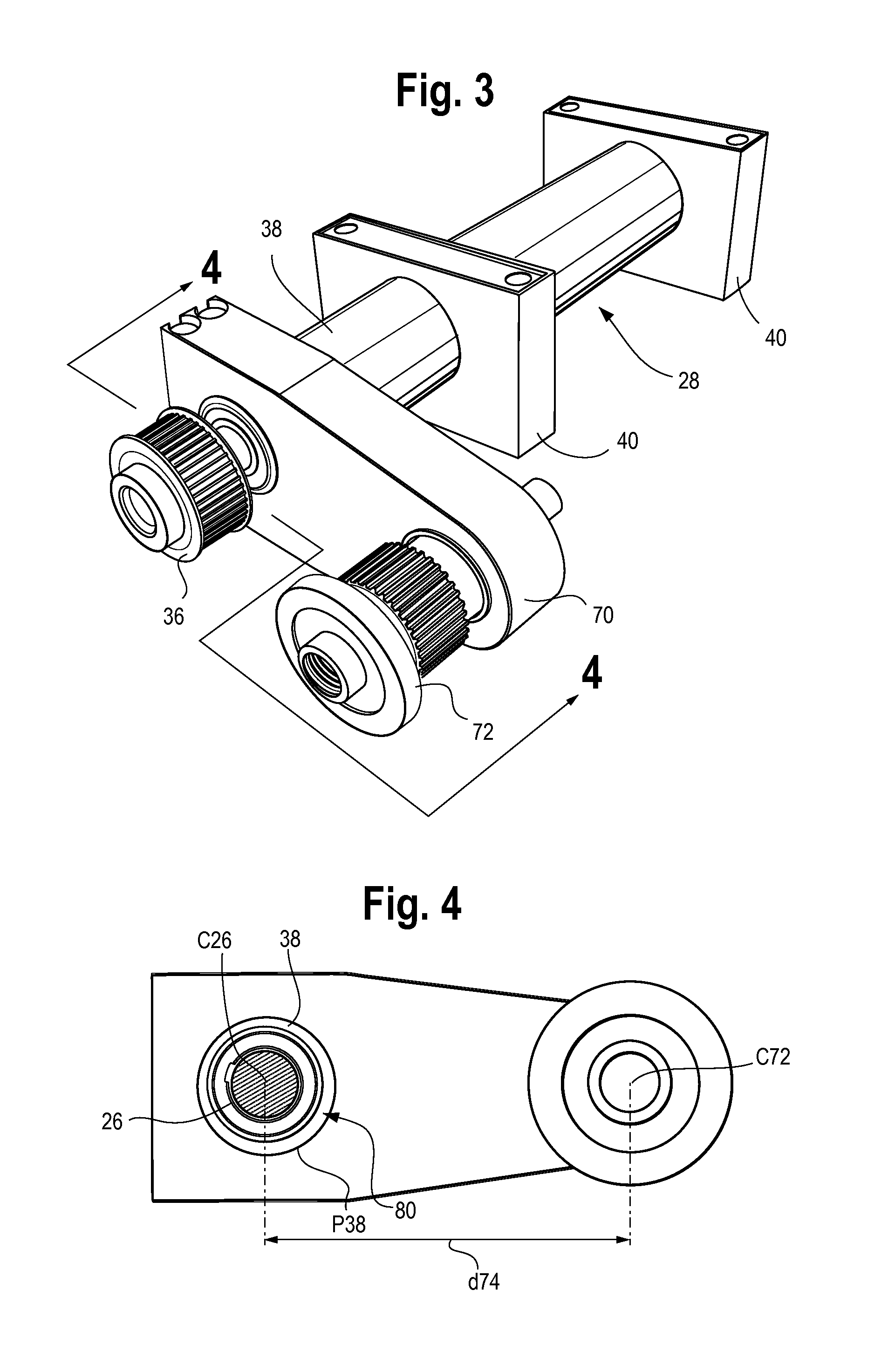
[0038]Referring now to the figures and in particular, to FIG. 1, there is shown an improved abrasive saw 10 embodying the principles of the present invention. In this illustration, the saw is shown with the hood and abrasive wheel removed for clarity of illustration. The saw 10 includes, generally, a base 12, a cutting region 14 with an ...


PUM

PropertyMeasurementUnit
Speedaaaaaaaaaa
Distanceaaaaaaaaaa
Tensionaaaaaaaaaa

Abstract

An abrasive saw having an associated cutting wheel is used for cutting objects. The saw includes a base, a cutting assembly operably mounted to the base and a controller. The cutting assembly includes a pivot shaft, a drive shaft operably mounted to the pivot shaft, a drive, and a drive wheel. A flexible drive element operably connects the drive shaft and a drive wheel. The distance between the drive wheel axis of rotation and the drive shaft axis of rotation is variable to increase or decrease a tension in the flexible drive element. A feed table is operably mounted to the base and is movable forward and rearward in a direction of rotation of the associated cutting wheel. The cutting wheel is lockable in the cutting position and the feed table, with the object secured thereto, is moved, by the controller toward the associated cutting wheel to cut the object. An enclosure encloses the cutting assembly and has stationary sides and openable front and top panels hingedly mounted to one another and to a portion of one of the side panels to open as a unitary assembly for access to the cutting assembly.

Description

CROSS-REFERENCE TO RELATED APPLICATION DATA[0001]This application is national phase of PCT / US2010 / 029619 filed Apr. 1, 2010, and claims the benefit of priority of Provisional U.S. Patent Application Ser. No. 61 / 174,560, filed May 1, 2009.BACKGROUND OF THE INVENTION[0002]The present invention relates to an abrasive saw. More particularly, the present invention relates to an improved abrasive saw having novel blade and sample drive systems, improved working area / sample access, wear components, and sensor and control features.[0003]Abrasive saws are used in various industries, but in particular are used in the rough or gross preparation of samples / specimens for examination. For example, specimens such as metals or aggregates (concrete) are often microscopically examined to determine grain structure, composition, failures and the like.[0004]In preparing samples, the samples typically must be cut, polished and mounted for examination. The first part of that preparation process, the cutti...

Claims


Application Information

Patent Timeline
IPC IPC(8): B24B51/00B24B7/10
CPCB23D45/02F16P1/02B23D47/12B23D45/042
Inventor WEINGART, JOHN L.FRESON, LAWRENCE L.HART, MICHAEL F.BUCHANAN, ARNOLD
Owner ILLINOIS TOOL WORKS INC
Learn More