Gas Detection System

a gas detection and gas technology, applied in the construction details of gas analyzers, instruments, optical elements, etc., can solve the problems of small amount of air entering the sealed chamber of the generator, safety hazards, and inability to detect various common gases, such as hydrogen

Inactive Publication Date: 2012-05-03
GENERAL ELECTRIC CO
View PDF7 Cites 27 Cited by
  • Summary
  • Abstract
  • Description
  • Claims
  • Application Information

AI Technical Summary

Benefits of technology

[0005]In another embodiment in accordance with aspects of the present invention, a gas detection system is provided for identifying a gas. The gas detection system includes an optical sensing fiber with a plurality of gas sensors, each gas sensor including a fiber Bragg grating positioned at a respective grating location along the optical sensing fiber and a sensing layer affixed to an exterior surface of the optical sensing fiber at each grating location. The sensing layer of each gas sensor is configured with a thermal sensitivity tuned to detect a gas with a heat transfer coefficient within a range. A respective exchange of heat energy between the a sensing layer and the gas within the heat transfer coefficient range induces a shift in the Bragg resonant wavelength at the respective grating location that exceeds a threshold shift required for detection of the gas within the range of the heat transfer coefficient.

Problems solved by technology

However, a small amount of air may penetrate the sealed chamber of the generator.
However, the generator case initially contains pure hydrogen gas, and may cause a safety hazard if the case was prematurely opened.
However, these conventional techniques have several drawbacks, such as not providing a single gas sensor which is capable of sensing a wide range of gases, thereby necessitating a separate sensor / system for different gases.
Additionally, for example, infrared absorption is used to sense a limited amount of gases, such as hydrocarbon-based gases, but is incapable of sensing various common gases, such as hydrogen.
Additionally, for example, a conventional thermal conductivity detection technique is used to sense certain gases, but is less accurate at sensing a wide range of gases, based on a lack of required thermal sensitivity and baseline drift.

Method used


Image

  • Gas Detection System
  • Gas Detection System
  • Gas Detection System

Examples


Embodiment Construction

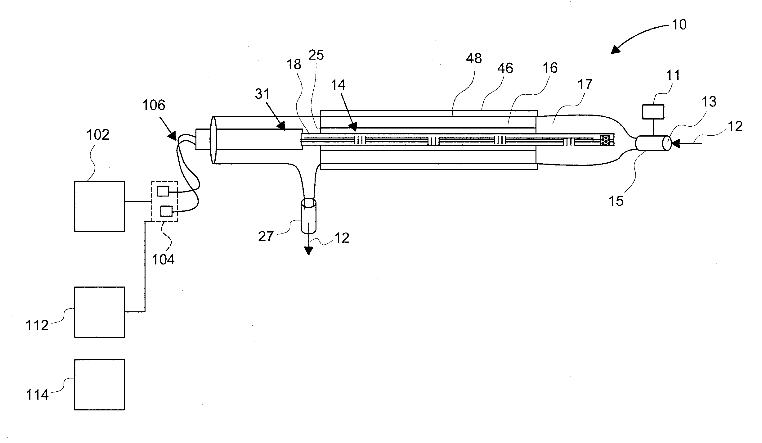
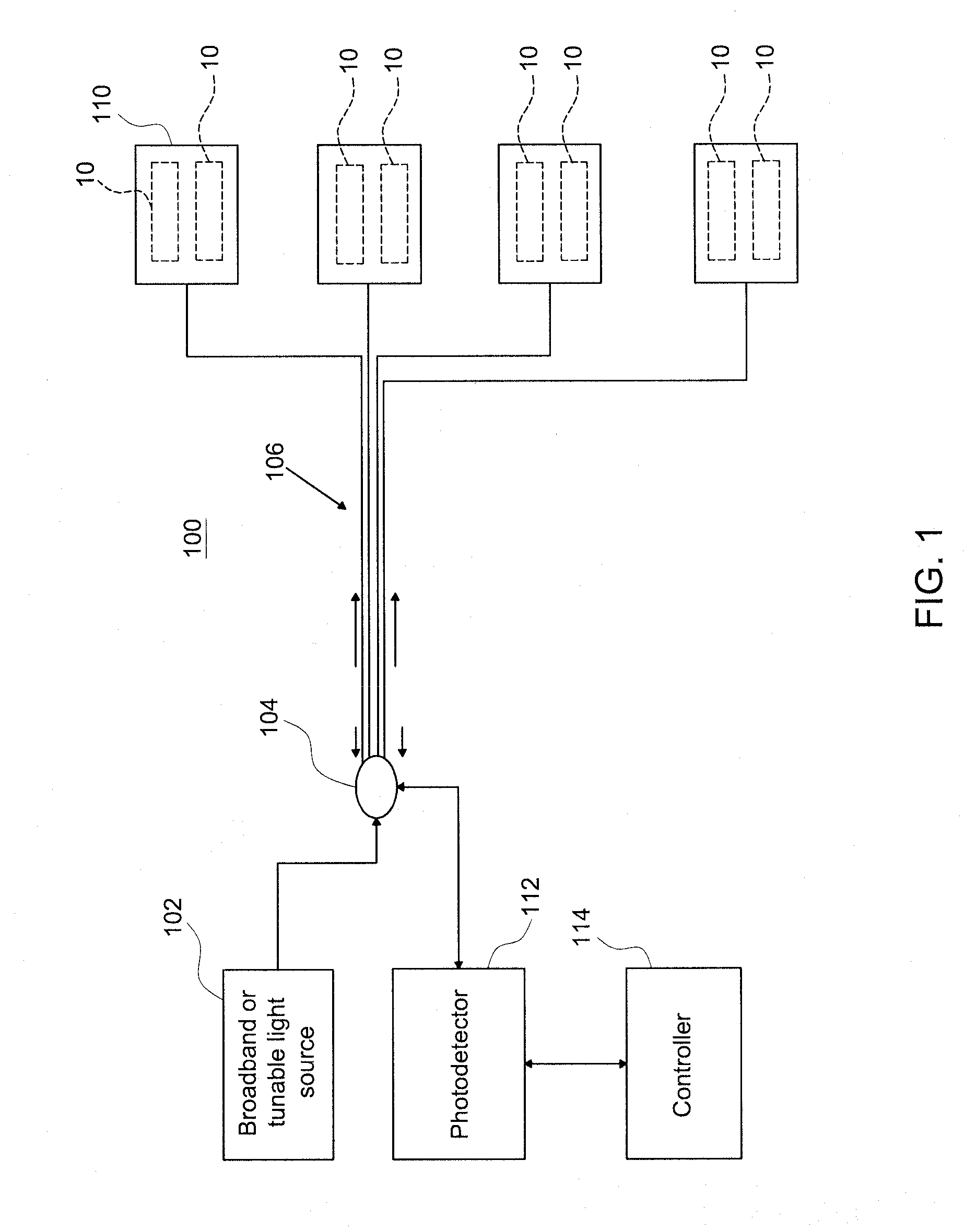
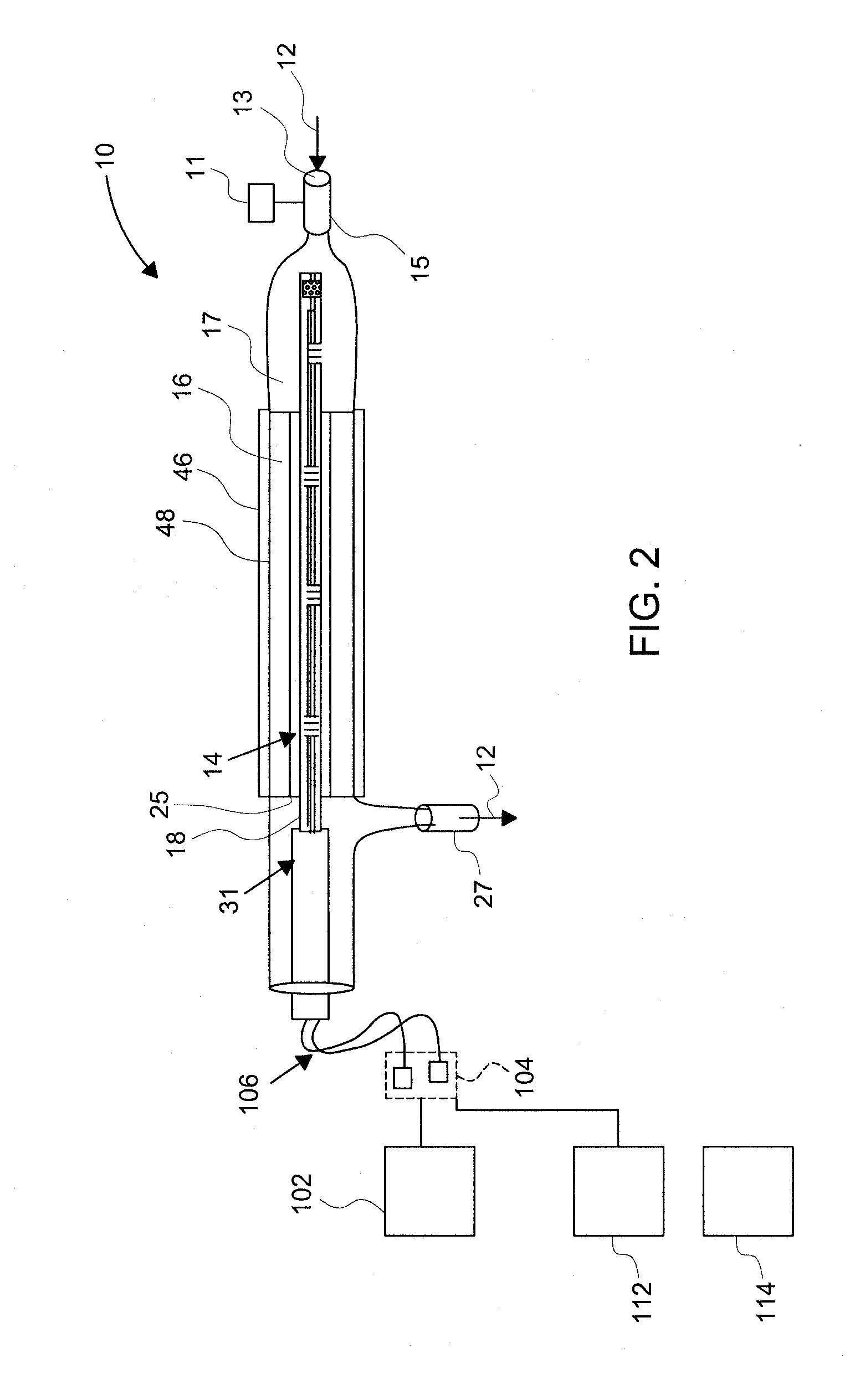
[0016]Aspects of the present invention discuss the sensing and identification of a gas and gas composition, including a multiple single-component pure gas, a two-component binary gas (a gas mixture of two pure gases), or a multi-component gas or multi-gas (a gas mixture of more than two pure gases). For example, if a pure gas is input into the sensor system, an identification of the gas, such as H2 gas or N2 gas, will be determined, based on a wavelength shift from a fiber gas sensor (FGS). In another example, if a binary gas is input into the sensor system, an identification of each pure gas within the binary gas, as well as the relative concentrations of each pure gas will be provided, such as 96% CO2 and 4% H2, for example. In an exemplary embodiment, for a binary gas formed from a first and second single-component gas, the first single-component gas may induce a wavelength shift of Δλ1, and the second single-component gas may induce a wavelength shift of Δλ2, while the binary ga...


PUM

PropertyMeasurementUnit
temperatureaaaaaaaaaa
threshold wavelengthaaaaaaaaaa
inlet temperatureaaaaaaaaaa

Abstract

A gas detection system is provided for identifying a gas. The gas detection system includes a sensing module with a hollow chamber enclosed by a chamber housing. Additionally, the sensing module includes an optical sensing fiber positioned within the hollow chamber. The optical sensing fiber includes a gas sensor including a fiber Bragg grating positioned at a grating location along the optical sensing fiber, and a sensing layer affixed to an exterior surface of the optical sensing fiber at the grating location. After the gas is directed into the hollow chamber, the sensing layer and the gas exchange heat energy, based in part on a heat transfer coefficient of the gas. The exchange of the heat energy induces a shift in a Bragg resonant wavelength of the fiber Bragg grating which exceeds a threshold shift required for detection, where the shift is used to identify the gas.

Description

BACKGROUND OF THE INVENTION[0001]In a variety of applications in which a gas is present, it may be necessary to know the identity of the gas. For example, a hydrogen-cooled generator typically uses a high purity of hydrogen gas which flows within sealed chambers of the generator for maintaining power generation efficiency. However, a small amount of air may penetrate the sealed chamber of the generator. Thus, a gas analyzer may be needed, to determine the hydrogen gas purity within the generator, to ensure that the purity of hydrogen gas is within a concentration range, such as 95-98%, for example. In the event that the generator encounters an operating problem, it may be necessary to open a generator case, in order to troubleshoot the problem. However, the generator case initially contains pure hydrogen gas, and may cause a safety hazard if the case was prematurely opened. Thus, a secondary gas such as carbon dioxide (CO2) or nitrogen gas (N2) may be used to purge the generator cas...

Claims


Application Information

Patent Timeline
Patent Type & Authority Applications(United States)
IPC IPC(8): G01N25/00
CPCG01N21/774G01N33/005G01N33/004G01N21/783G01N21/41
Inventor XIA, HUAGUIDA, RENATOWU, JUNTAOBUSBOOM, AXELBANTUG, ANICETOCHAMARTHY, PRAMOD
Owner GENERAL ELECTRIC CO
Why Eureka
Try Eureka