Lighting device, display device and television receiver
a technology of display device and light source, which is applied in the field of light source device, display device and television receiver, can solve the problems of uneven brightness and exposure of light source, and achieve the effect of suppressing uneven brightness
- Summary
- Abstract
- Description
- Claims
- Application Information
AI Technical Summary
Benefits of technology
Problems solved by technology
Method used
Image

Examples
first embodiment
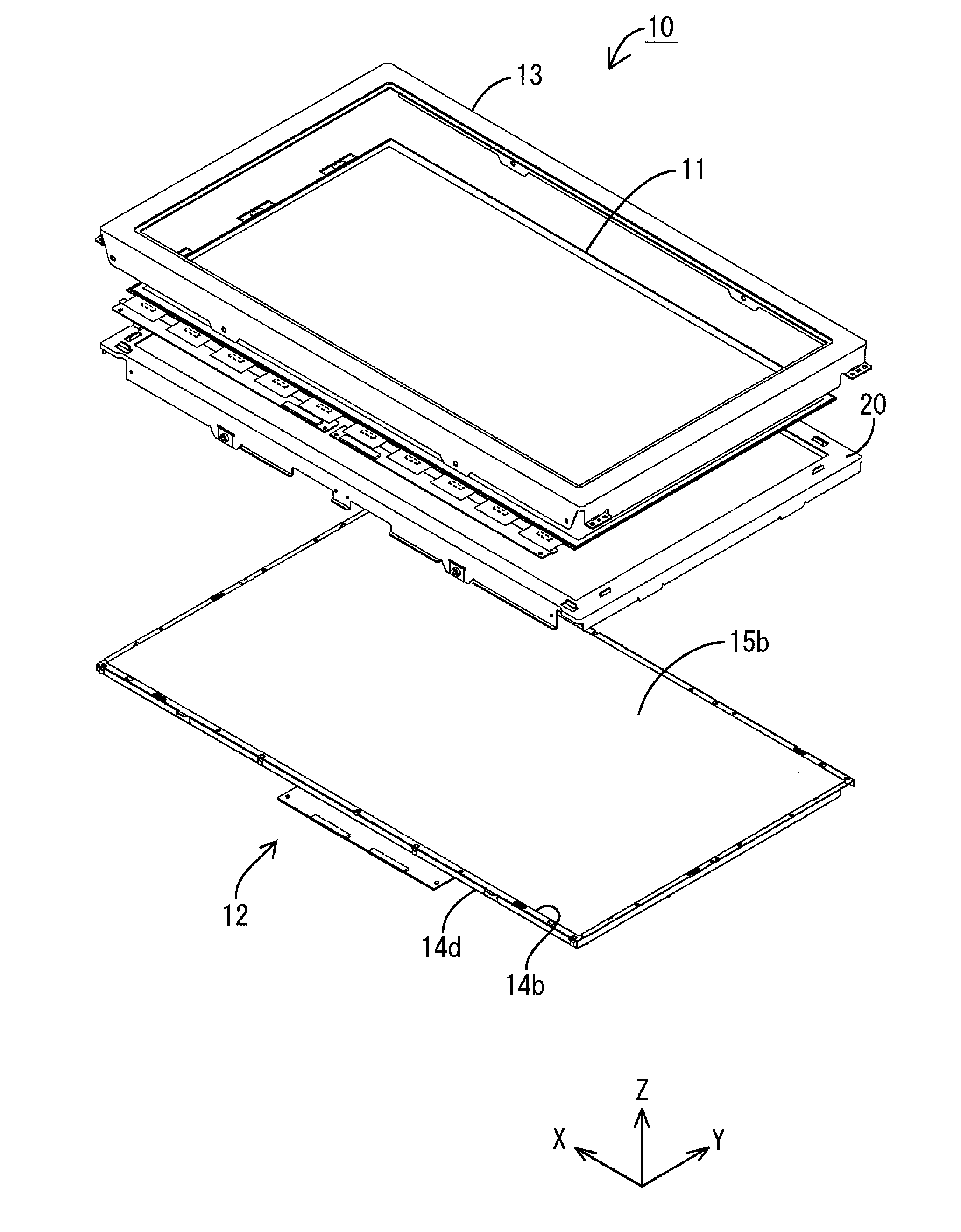
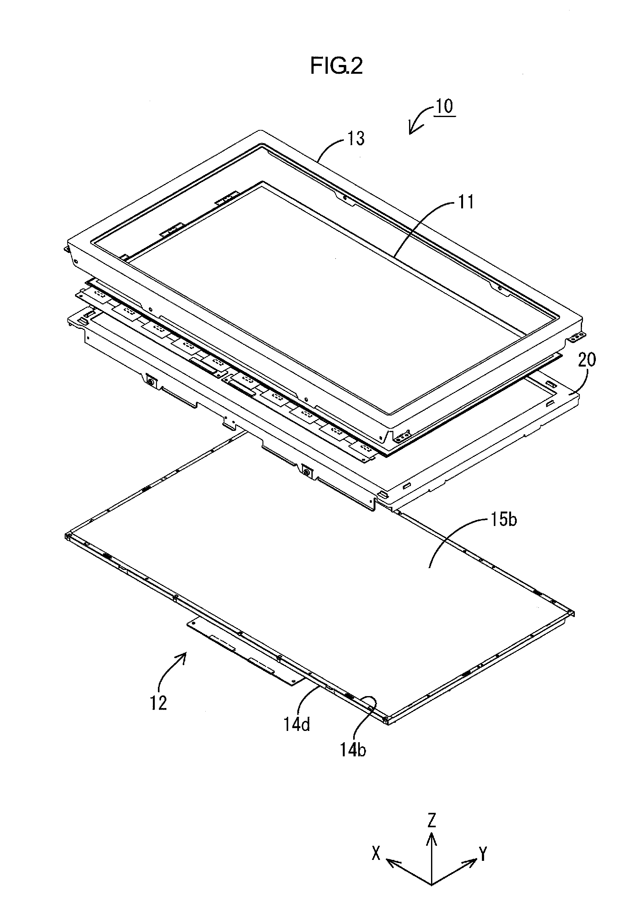
[0031]A First embodiment of the present invention will be described with reference to FIGS. 1 to 8. Note that each of the drawings in the present embodiment has a part showing an X-axis, a Y-axis and a Z-axis, and is illustrated such that directions shown therein correspond to the directions of the respective axes. Additionally, the upper side shown in FIG. 4 is the front side, and the lower side therein is the back side.
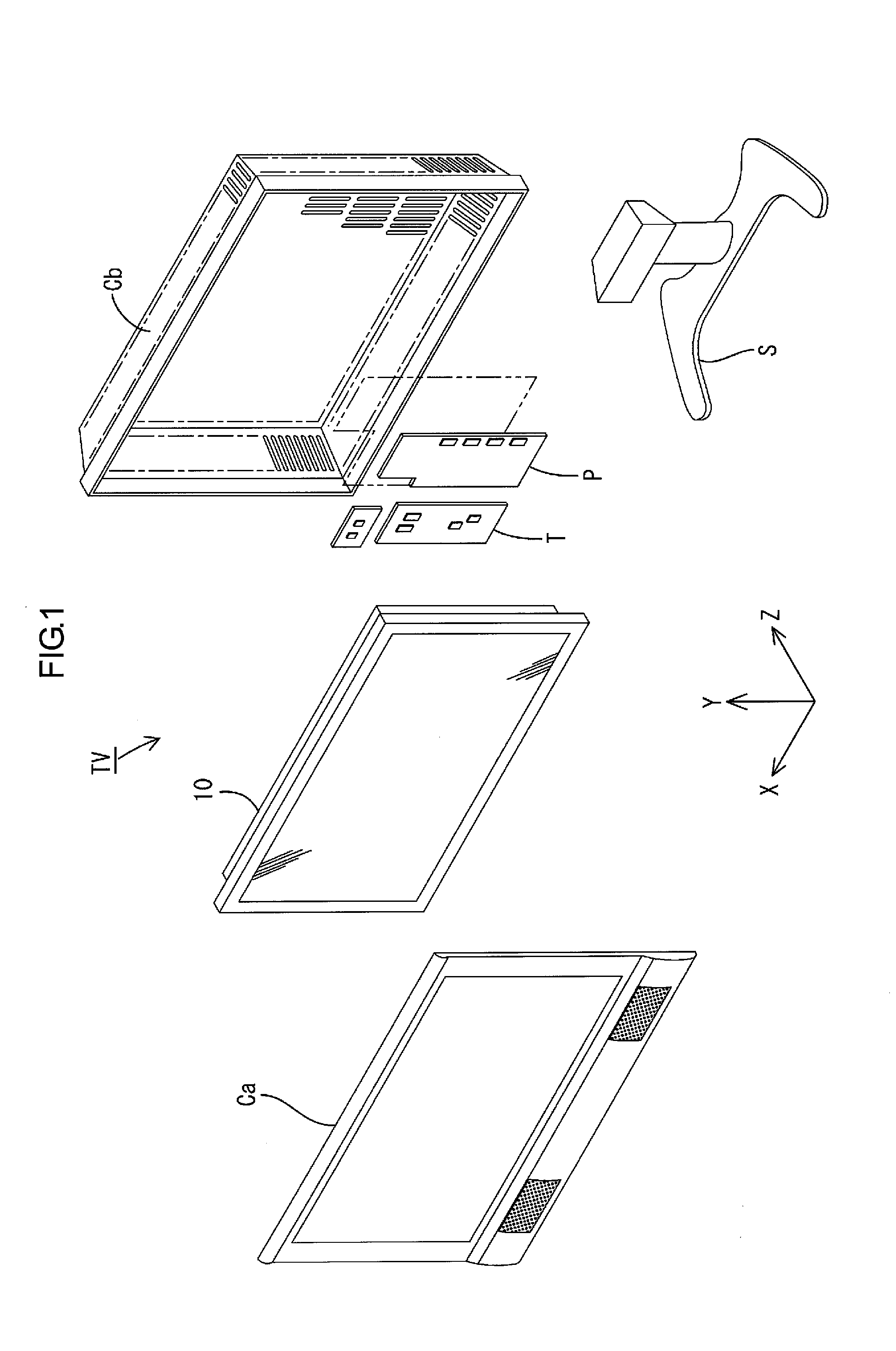
[0032]A television receiver TV according to the present embodiment, as shown in FIG. 1, includes a liquid crystal display device 10 (display device), front and back cabinets Ca and Cb, a power supply P and a tuner T. The front and back cabinets Ca and Cb sandwich from the front and back sides, and thus house, the liquid crystal display device 10. The television receiver TV is supported by a stand S so that the display surface thereof may go along the vertical direction (Y-axis direction). The liquid crystal display device 10 as a whole has a horizontally long, recta...
second embodiment
[0062]Next, a Second embodiment of the present invention will be described with reference to FIGS. 9, 10 and 20. In the second embodiment described herein, a structure for attachment between a board mounted connector and a relay component are different from that of the first embodiment. Note that, in the second embodiment described herein, the same reference symbols are used for parts having the same names as those in the first embodiment described above, and redundant explanations on structures, operations and effects are omitted.
[0063]The present embodiment employs a configuration which makes it possible to attach a relay component 163 to a board mounted connector 161 from the outside of the bottom plate 14a of the chassis 14. Specific configurations will be described below. On the inner (front) surface of the bottom plate 14a of the chassis 14, parts corresponding to the board mounted connectors 161 are dented toward the back side, whereby connector housing portions 114A are form...
third embodiment
[0069]Next, a third embodiment of the present invention will be described with reference to FIG. 11. Note that, in the third embodiment described herein, the same reference symbols are used for parts having the same names as those in the above described embodiments, and redundant explanations on structures, operations and effects are omitted.
[0070]In the second embodiment described above, the top end portions 161A of the board mounted connectors 161 are allowed to be inserted into the insertion holes 114D formed in the chassis 14. In contrast, the present embodiment employs a configuration in which, as shown in FIG. 11, top end portions 265A (parts of a relay component) projecting toward the front side are formed on the relay connector 265 and inserted into the insertion holes 114D. This configuration makes it possible to attach a relay component 263 to board mounted connectors 261 by inserting the top end portions 265A of the relay component 263 into the insertion holes 114D from t...
PUM
 Abstract
Description
Claims
Application Information
 - R&D
- Intellectual Property
- Life Sciences
- Materials
- Tech Scout
- Unparalleled Data Quality
- Higher Quality Content
- 60% Fewer Hallucinations
Browse by: Latest US Patents, China's latest patents, Technical Efficacy Thesaurus, Application Domain, Technology Topic, Popular Technical Reports.
© 2025 PatSnap. All rights reserved.Legal|Privacy policy|Modern Slavery Act Transparency Statement|Sitemap|About US| Contact US: help@patsnap.com