Image display device using diffractive device

Active Publication Date: 2012-05-03
SAMSUNG DISPLAY CO LTD
View PDF5 Cites 49 Cited by
  • Summary
  • Abstract
  • Description
  • Claims
  • Application Information

AI Technical Summary

Benefits of technology

[0008]At least one embodiment of the present invention has been made in a

Problems solved by technology

However, a display device that includes both the lens and th

Method used


Image

  • Image display device using diffractive device
  • Image display device using diffractive device
  • Image display device using diffractive device

Examples


Embodiment Construction

[0047]The present invention will be described more fully hereinafter with reference to the accompanying drawings, in which exemplary embodiments of the invention are shown.

[0048]In the drawings, the thickness of layers, films, panels, regions, etc., may be exaggerated for clarity. Like reference numerals designate like elements throughout the specification. It will be understood that when an element such as a layer, film, region, or substrate is referred to as being “on” another element, it can be directly on the other element or intervening elements may also be present.

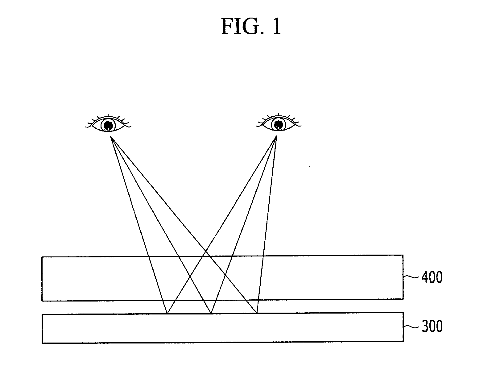
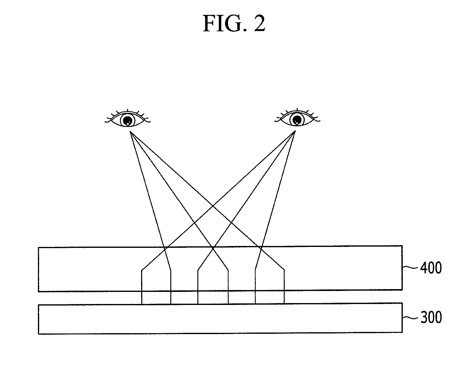
[0049]FIGS. 1 and 2 are a schematic structure of an image display device and a diagram showing a method of forming a 2D image and a 3D image, respectively according to an exemplary embodiment of the present invention.

[0050]Referring to FIGS. 1 and 2, the image display device includes a display panel 300 displaying an image and a diffractive device 400 positioned in front of a surface on which the image of the display...


PUM


Abstract

An image display device includes a display panel displaying an image and a diffractive device. The diffractive device operates in a 2D mode to enable perception of a 2D image from the image of the display panel and in a 3D mode to enable perception of the image of the display panel as a 3D image. The diffractive device includes a plurality of unit devices. When the diffractive device operates in 3D mode, at least one of the plurality of unit devices operates in a lens mode and a barrier mode during different periods.

Description

CROSS-REFERENCE TO RELATED APPLICATION[0001]This application claims priority to Korean Patent Application No. 10-2010-0106853 filed in the Korean Intellectual Property Office on Oct. 29, 2010, the disclosure of which is incorporated by reference herein.BACKGROUND[0002](a) Technical Field[0003]Embodiments of the present invention relate to an image display device using a diffractive device.[0004](b) Discussion of Related Art[0005]A three dimensional (3D) image may be visualized by stereovision through both eyes. A binocular disparity is generated by a visual disparity between both eyes, i.e., the distance between both eyes. For example, the left and right eyes view different 2D images and when both images are transferred to the brain through the retina, the brain fuses the images to create a 3D image.[0006]Stereoscopy is a method of displaying stereoscopic 3D images. A 3D image display device may include a barrier and a lenticular lens (e.g., a kind of cylindrical lens). The barrier ...

Claims


Application Information

Patent Timeline
IPC IPC(8): G02F1/1335G02B27/22G02B30/28G02B30/31
CPCG09G3/003G09G2310/066G02B27/2214G02F1/1323G02F1/134309G02F1/29G02B5/1885G02B30/31G02B30/28H04N13/305H04N13/31H04N13/359H04N2013/405G02B30/27
Inventor YOON, IL-YONGJEONG, SEUNG-JUNKIM, JIN-HWANYUN, HAE-YOUNGLEE, SEUNG-HOONKIM, IL-JOOYI, JUNG-HWAN
Owner SAMSUNG DISPLAY CO LTD
Why Eureka
Try Eureka