Additive Manufacturing-Based Compact Epifluorescence Microscope

a technology of epifluorescence microscope and additive manufacturing, which is applied in the field of additive manufacturing-based compact epifluorescence microscope, can solve the problems of not being able to capture structures that are practical, and achieve the effects of reducing cost, weight, and stiffness, and sacrificing optical sensitivity

Inactive Publication Date: 2012-05-03
CUMMINGS ERIC B +2
View PDF7 Cites 33 Cited by
  • Summary
  • Abstract
  • Description
  • Claims
  • Application Information

AI Technical Summary

Benefits of technology

[0003]The object of the present invention is to create an epifluorescence microscope that does not suffer from these conventional drawbacks. Embodiments of the present invention achieve a compact form factor without sacrificing optical sensitivity by the novel use of combined optic mounts and light baffles constructed using additive manufacturing processes. The use of additive manufacturing enables stray-light-capturing structures that are not practical to make by other techniques. The compact form of the microscope reduces cost, weight, and improves stiffness with no reduction in optical performance over larger conventional microscopes. Some embodiments of the present invention do not require installation of filters by an operator, reducing the likelihood of dust and contamination on optical surfaces. Some embodiments of the present invention employ a novel light path that avoids passing the fluorescent light through off-axis elements. This optical arrangement provides for the use of a microscope objective having a finite corrected-image distance, such as a DIN objective, rather than infinity-corrected objective that require additional optical elements to form an image. The reduction in complexity can both reduce system cost and improve optical performance by reducing Fresnel losses and imaging artifacts from Fresnel reflections.

Problems solved by technology

The use of additive manufacturing enables stray-light-capturing structures that are not practical to make by other techniques.

Method used


Image

  • Additive Manufacturing-Based Compact Epifluorescence Microscope
  • Additive Manufacturing-Based Compact Epifluorescence Microscope
  • Additive Manufacturing-Based Compact Epifluorescence Microscope

Examples


Embodiment Construction

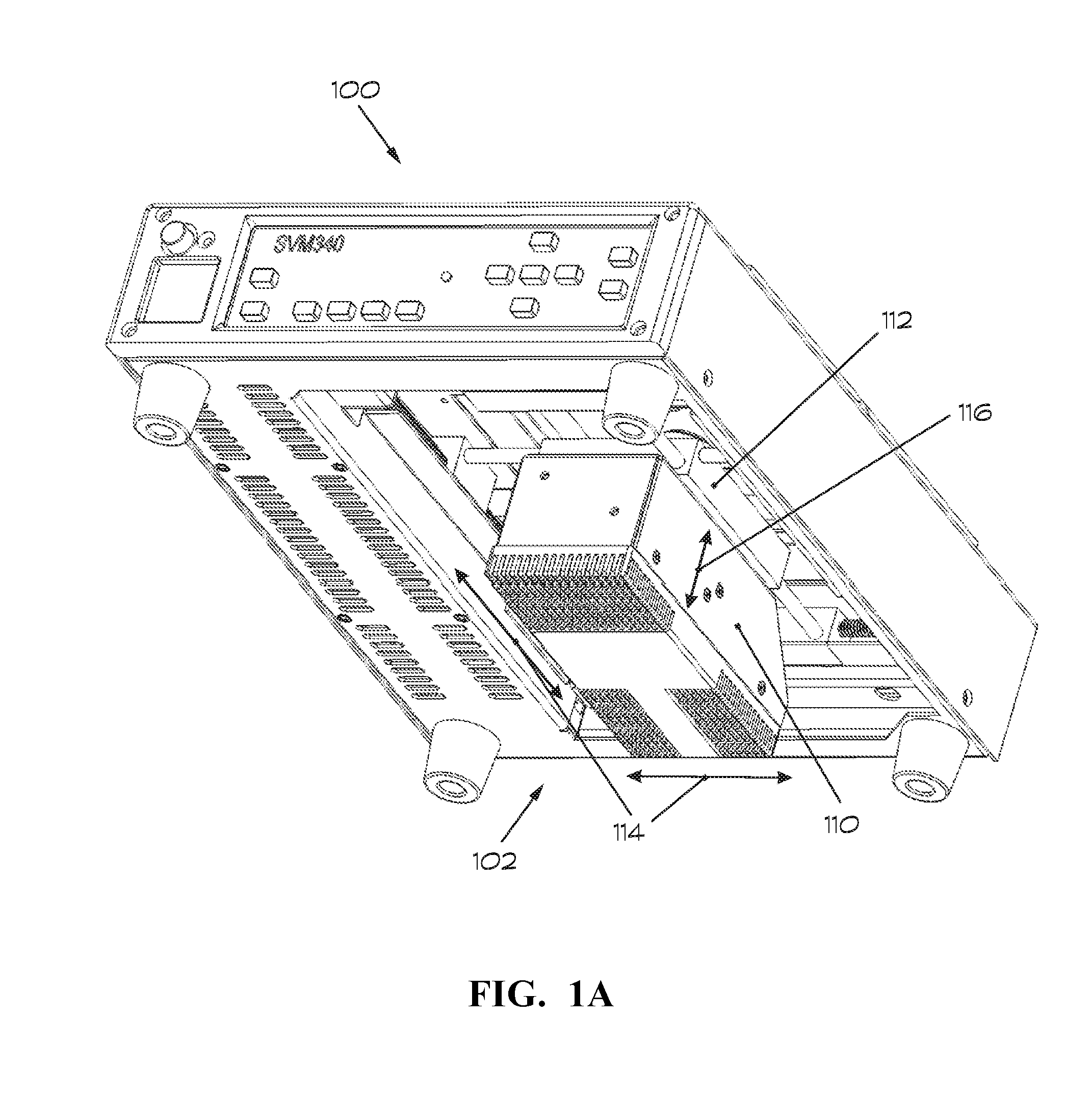
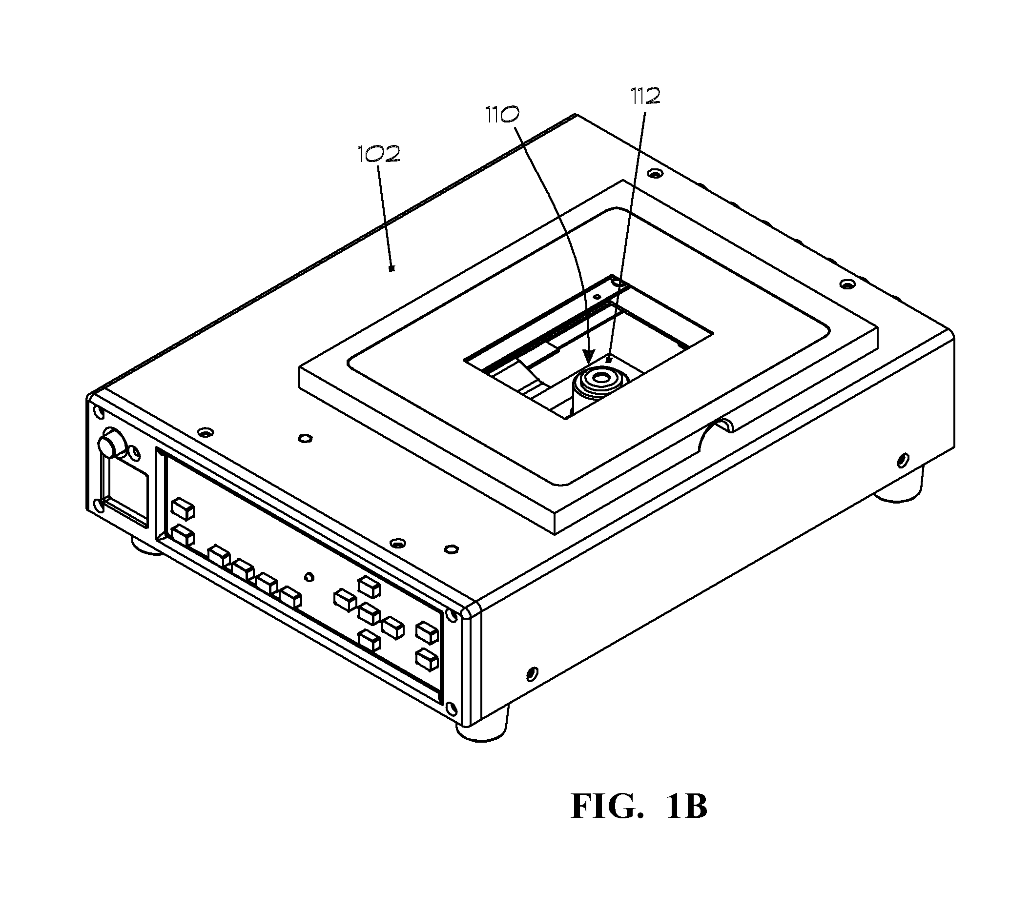
[0016]FIG. 1A shows a bottom perspective view of a video microscopy system 100 containing an epifluorescence microscope 102 according to an embodiment of the present invention. The video microscopy system is disclosed in U.S. patent application Ser. No. 11 / 526,158, which was published as U.S. Patent Publication 2007-0081078 A1 on Apr. 12, 2007 and which is incorporated herein by reference. In this embodiment, a motorized traverse 112 provides panning motion 114 and focus motion 116. FIG. 1B shows a top perspective view of the microscopy system.

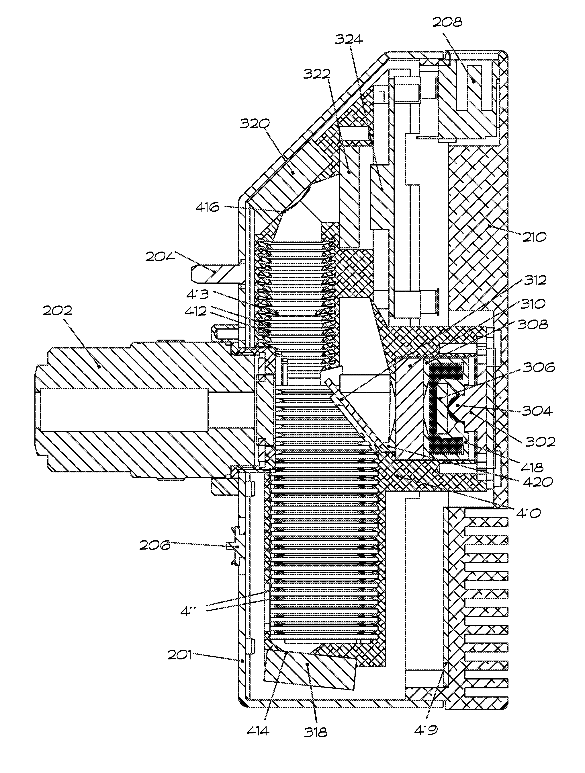
[0017]FIGS. 1A and 1B show the epifluorescence microscope 102 according to an embodiment of the present invention in a motorized traverse. A housing 110 houses the entire epifluorescence optical train, camera, illuminator, and illuminator-strobing electronics such that the output of the microscope 102 is an electronic signal that conveys the epifluorescence image. In some embodiments, the image output in an analog format. In other embodiments,...


PUM


Abstract

An epifluorescence microscope achieves a compact form factor without sacrificing optical sensitivity by the novel use of combined optic mounts and light baffles constructed using additive manufacturing processes. The use of additive manufacturing enables stray-light-capturing structures that are not practical to make by other techniques. Some embodiments of the present invention do not require installation of filters by an operator, reducing the likelihood of dust and contamination on optical surfaces. Some embodiments of the present invention employ a novel light path that avoids passing the fluorescent light through off-axis elements. This optical arrangement provides for the use of a microscope objective having a finite corrected-image distance, such as a DIN objective, rather than infinity-corrected objective that require additional optical elements to form an image. The reduction in complexity can both reduce system cost and improve optical performance by reducing Fresnel losses and imaging artifacts from Fresnel reflections.

Description

BACKGROUND OF THE INVENTION[0001]Fluorescence microscopy is an essential tool in microbiology and medicine. In fluorescence, light of one wavelength is absorbed by molecules and re-emitted at a different wavelength. The absorption and emission wavelengths depend on the specific molecules. The separation in wavelengths between absorption and emission allows the background of non-fluorescent light to be filtered from the fluorescence signal, enhancing the sensitivity and providing for quantitative image analysis. In epifluorescence microscopy, the excitation light passes to the sample through the microscope objective that captures the fluorescent light, requiring access to one side of a sample only and allowing fluorescence microscopy on non-transparent objects. An assembly of precision filters and beam-splitters is typically used in epifluorescence. These elements are often conventionally mounted in an interchangeable filter cube that is inserted into a suitably designed microscope b...

Claims


Application Information

Patent Timeline
Patent Type & Authority Applications(United States)
IPC IPC(8): G02B21/06G02B21/00
CPCG02B21/0008G02B21/082G02B21/16G02B21/24B33Y80/00
Inventor CUMMINGS, ERIC BPACE, KIRSTEN KPHILPOTT, ROGER A
Owner CUMMINGS ERIC B
Why Eureka
Try Eureka