Forming die assembly for microcomponents

a micro-component and assembly technology, applied in the direction of shaping presses, manufacturing tools, presses, etc., can solve the problems of difficult use of raw materials and inefficient production methods, and achieve the effects of improving the flowability of raw materials, easy filling of raw materials, and easy supply of raw materials

Active Publication Date: 2012-05-03
RESONAC CORP
View PDF12 Cites 5 Cited by
  • Summary
  • Abstract
  • Description
  • Claims
  • Application Information

AI Technical Summary

Benefits of technology

[0006]The present invention has been completed in view of the above circumstances, and an object of the present invention is to provide a forming die assembly for microcomponents. According to the forming die assembly, a raw material with a metal powder and a binder having plasticity (hereinafter called a “raw material”) is easily supplied to dies and is thereby efficiently compacted, whereby a green compact is obtained.
[0008]According to the present invention, the raw material is supplied through the supply path into the cavity of the forming die, and the raw material in the cavity is compacted into a green compact by the punch. Then, the forming die assembly is opened, whereby the green compact is obtained. By repeating the above operation, green compacts are continuously obtained. The raw material in a small amount is easily successively filled in the cavity by supplying the raw material through the supply path. Moreover, it is not required to pull out the punch for the supply of the raw material. Accordingly, the green compacts are efficiently produced.
[0009]In the present invention, the forming die may be provided with a storage portion which is connected to the supply path and is used for storing the raw material. In addition, the storage portion may be formed so that a plunger is slidably inserted thereinto, and the plunger may supply the raw material stored in the storage portion via the gate into the cavity. In this case, since the forming die has the storage portion for supplying the raw material to the supply path, it is not required to arrange a storage portion separately and to connect the storage portion to the supply path. Therefore, the forming die assembly of the present invention can be independently operated, and the supply route of the raw material is simple.
[0012]Moreover, in the present invention, in order to improve the flowability of the raw material and to easily fill the raw material into the cavity, the forming die is preferably provided with a heating means for heating the raw material that passes through the supply path.
[0013]According to the present invention, a forming die assembly for microcomponents is provided, and the raw material is easily supplied to the forming die, and thereby a green compact is efficiently obtained.

Problems solved by technology

In this case, since the raw material is different from a raw powder, which is used in an ordinary powder metallurgy process, and has plasticity, the raw material is difficult to use.
However, in a case of forming a microcomponent, since the amount of raw material required for one compacting is extremely small, this production method is not efficient.

Method used


Image

  • Forming die assembly for microcomponents
  • Forming die assembly for microcomponents
  • Forming die assembly for microcomponents

Examples


Embodiment Construction

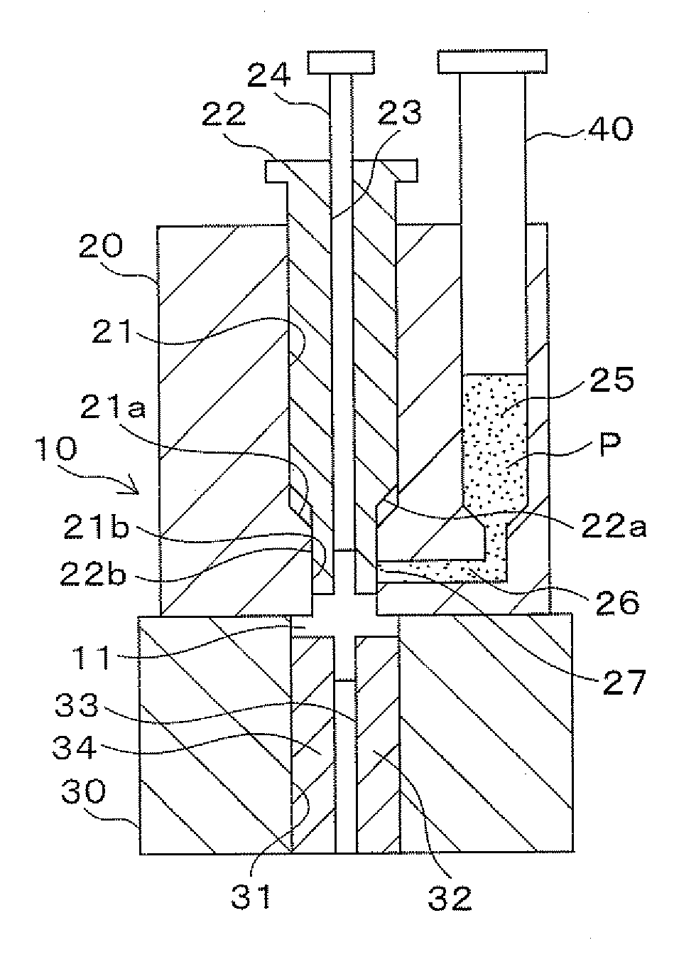
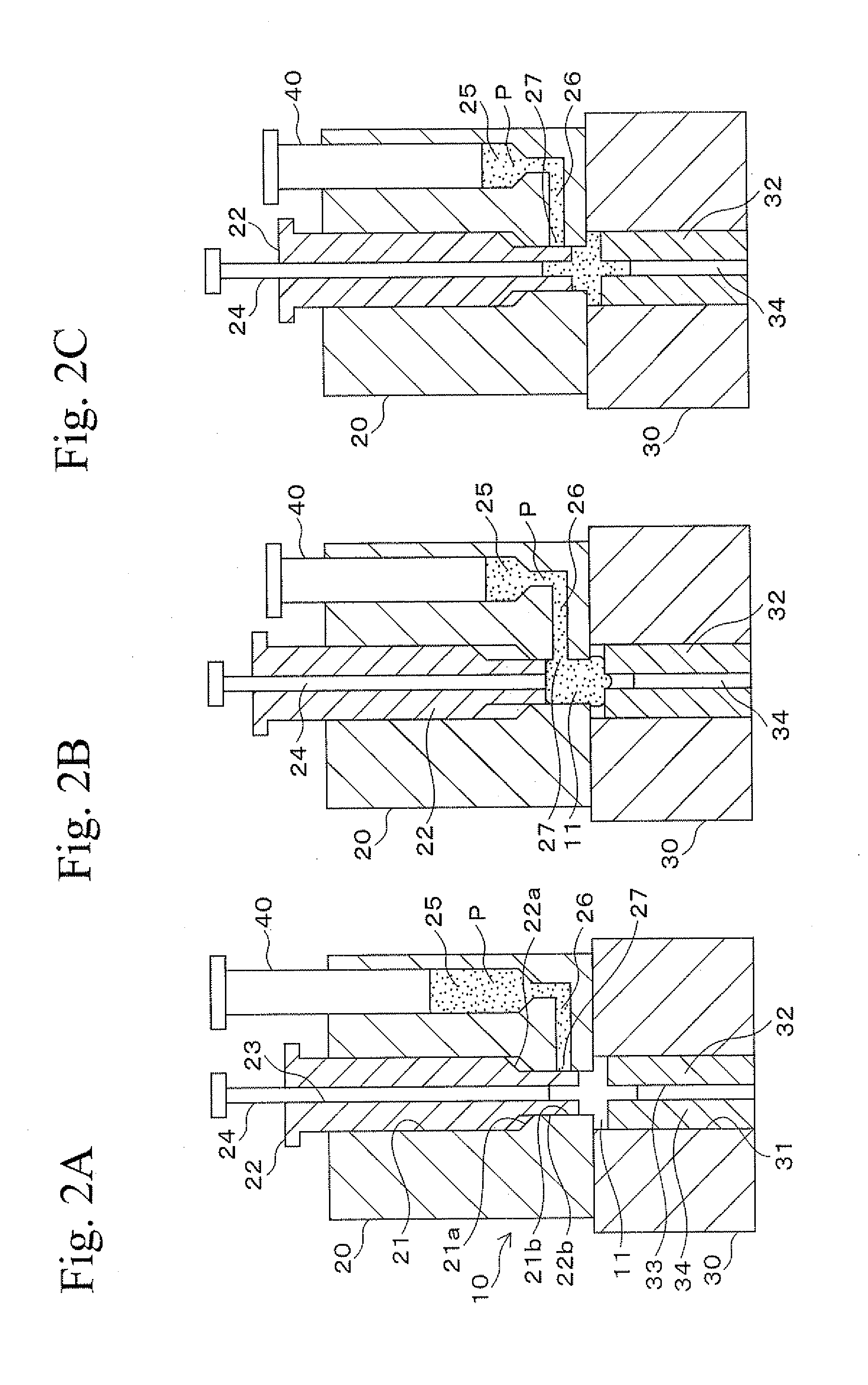
[0019]Embodiments of the present invention will be described with reference to the figures hereinafter.

(1) Microgear

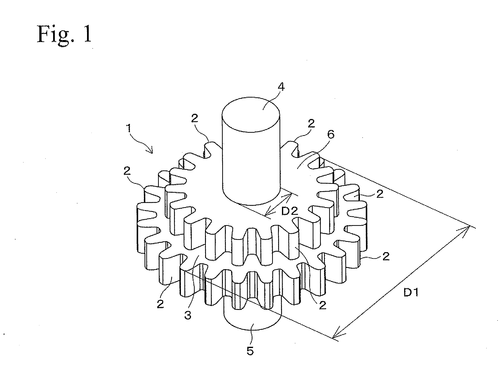
[0020]FIG. 1 shows a microgear of a microcomponent. The gear 1 is obtained by sintering a green compact that is formed by a forming die assembly of an embodiment. The gear 1 is a two-step gear in which a spur wheel portion 6 is formed on a side (upper side in FIG. 1) of a spur wheel portion 3. The spur wheel portion 6 has a smaller diameter, and the spur wheel portion 3 has a larger diameter. The gear 1 has shaft portions 4 and 5. The shaft portion 4 projects from the spur wheel portion 6. The shaft portion 5 projects from the spur wheel portion 3 and has the same diameter as that of the shaft portion 4. Each of the spur wheel portions 3 and 6 is formed with plural teeth 2 at the outer circumferential surface thereof. The gear 1 may have the following dimensions. For example, the spur wheel portion 3 has an outer diameter D1 of several hundred micrometers to several mi...


PUM

PropertyMeasurementUnit
diameter D2aaaaaaaaaa
volume %aaaaaaaaaa
plasticityaaaaaaaaaa

Abstract

A forming die assembly for microcomponents includes a forming die and a punch. The forming die is formed with a cavity, a punch hole connected to the cavity, and a supply path for supplying a raw material with a metal powder and a binder having plasticity. The supply path is connected to the cavity so as to have a gate therebetween and is used for supplying the raw material into the cavity. The punch is slidably inserted into the punch hole, and it opens and closes the gate by reciprocatory sliding. The punch closes the gate and compresses the raw material in the cavity into a green compact by sliding in the direction of the cavity.

Description

BACKGROUND OF THE INVENTION[0001]1. Technical Field[0002]The present invention relates to a forming die assembly including dies that may be used for producing microcomponents such as microgears. In the dies, a raw material with a metal powder and a binder having plasticity is compacted into a green compact with a shape similar to that of the microcomponent.[0003]2. Background Art[0004]Recently, in the production of digital home appliances, advanced medical equipment, and IT devices, there are trends toward decreasing dimensions and increasing performances of the devices. Therefore, requirements for decreasing dimensions and wall thicknesses have been increasing for components of such devices. In view of this, although microcomponents basically have small dimensions and thin walls, the microcomponents are also required to be even smaller and have thinner walls. A production method for such microcomponents is disclosed in Japanese Patent Application of Laid-Open No. 2006-344581. In th...

Claims


Application Information

Patent Timeline
Patent Type & Authority Applications(United States)
IPC IPC(8): B22F3/00
CPCB22F3/03B30B15/302B30B11/02
Inventor MURASUGI, NARUTOSHIMAEKAWA, KAZUNORIISHIJIMA, ZENZO
Owner RESONAC CORP
Why Eureka
Try Eureka