Apparatus and method of placement of a graft or graft system
a technology of graft and graft system, applied in the field of apparatus and method of graft or graft system placement, can solve the problems of complex arrangement of prior branch graft, and achieve the effect of improving the efficiency of branch graft deploymen
- Summary
- Abstract
- Description
- Claims
- Application Information
AI Technical Summary
Benefits of technology
Problems solved by technology
Method used
Image

Examples
Embodiment Construction
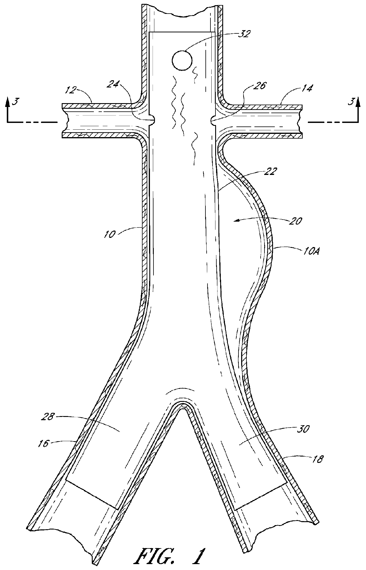
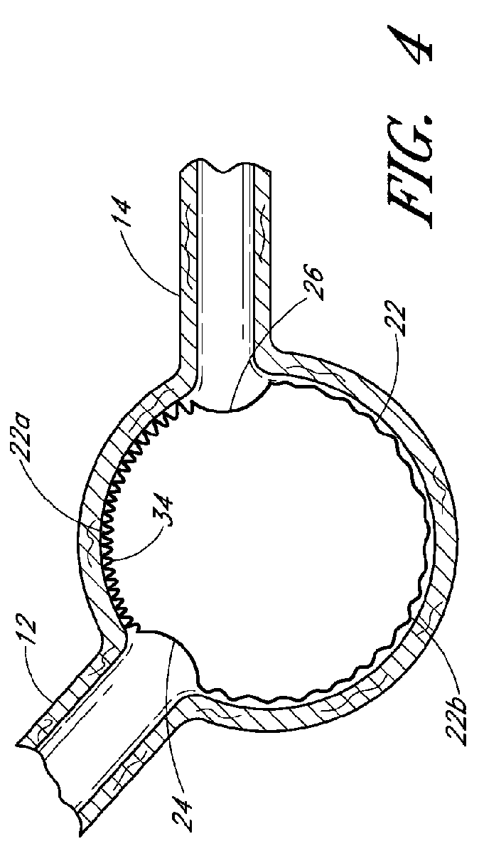
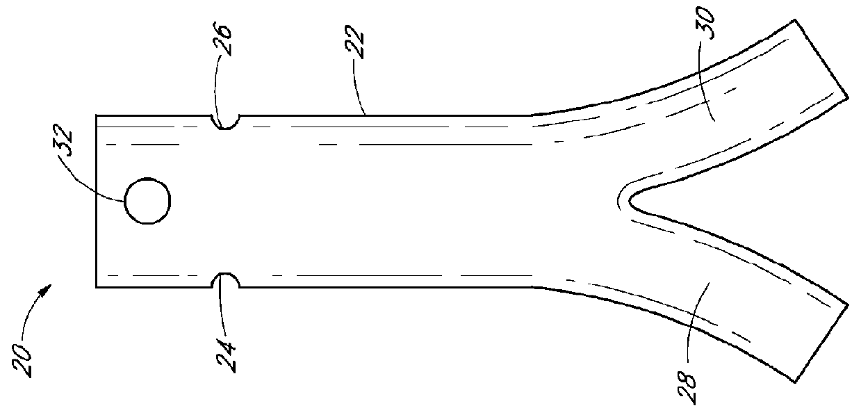
[0009]Designs and methods of placement of a branch graft or branch graft system having lateral openings in the main graft are disclosed. The main graft is positioned within the main blood vessel such as the aorta so that the lateral openings (also referred to herein as fenestrations) can be aligned with the branch blood vessels, to allow blood to flow through the openings in the main graft and into the branch vessels. The positions of the branch blood vessels can vary from one patient's anatomy to the next, the graft systems disclosed herein allow a surgeon to adjust the position of the fenestrations in the main body so as to align them with the branch vessels to improve the efficiency of branch graft deployment.
[0010]The branch graft system can comprise a tubular expandable main body and at least one fenestration or at least one branch graft at any desired location. The main graft body and / or the branch graft can be made from an expandable material, such as but not limited to ePTFE...
PUM
 Abstract
Description
Claims
Application Information
 - R&D
- Intellectual Property
- Life Sciences
- Materials
- Tech Scout
- Unparalleled Data Quality
- Higher Quality Content
- 60% Fewer Hallucinations
Browse by: Latest US Patents, China's latest patents, Technical Efficacy Thesaurus, Application Domain, Technology Topic, Popular Technical Reports.
© 2025 PatSnap. All rights reserved.Legal|Privacy policy|Modern Slavery Act Transparency Statement|Sitemap|About US| Contact US: help@patsnap.com