Radon migration of acoustic data

Active Publication Date: 2012-05-03
BAKER HUGHES INC
View PDF3 Cites 11 Cited by
  • Summary
  • Abstract
  • Description
  • Claims
  • Application Information

AI Technical Summary

Benefits of technology

[0007]Disclosed is a method implemented by a processor for imaging a formation penetrated by a borehole. The method includes: obtaining acoustic data in a depth-time domain using an acoustic downhole tool disposed at a depth in the borehole, the acoustic downhole tool comprising an acoustic source and an acoustic receiver; transforming the acoustic data in the depth-time domain into a Radon domain using a Radon transform; filtering the acoustic data in the Radon domain to increase a signal of interest in the acoustic data in the Radon domain; determining a location of a point in the formation that reflected acoustic energy emitted from the acoustic source to the acoustic receiver, the location of the point being represented in the Radon domain; and inverting the location of the point represented in the Radon domain into a radius-depth, r-z, domain to image the formation, the depth being a distance into the borehole and the radius being a radial distance from the borehole.
[0008]Also disclosed is an apparatus for imaging a formation penetrated by a borehole. The apparatus includes: an acoustic downhole tool configured to be disposed in the borehole. The tool includes an acoustic source configured to emit acoustic energy into the formation and an acoustic receiver configured to receive acoustic energy reflected by the formation and a processor coupled to the downhole tool and configured to implement a formation imaging method. The formation imaging method includes: obtaining acoustic data in a depth-time domain from the acoustic downhole tool disposed at a depth in the borehole; transforming the acoustic data in the depth-time domain into a Radon domain usi

Problems solved by technology

Several factors though, such as noise, can m

Method used


Image

  • Radon migration of acoustic data
  • Radon migration of acoustic data
  • Radon migration of acoustic data

Examples


Embodiment Construction

[0015]A detailed description of one or more embodiments of the disclosed apparatus and method presented herein by way of exemplification and not limitation with reference to the Figures.

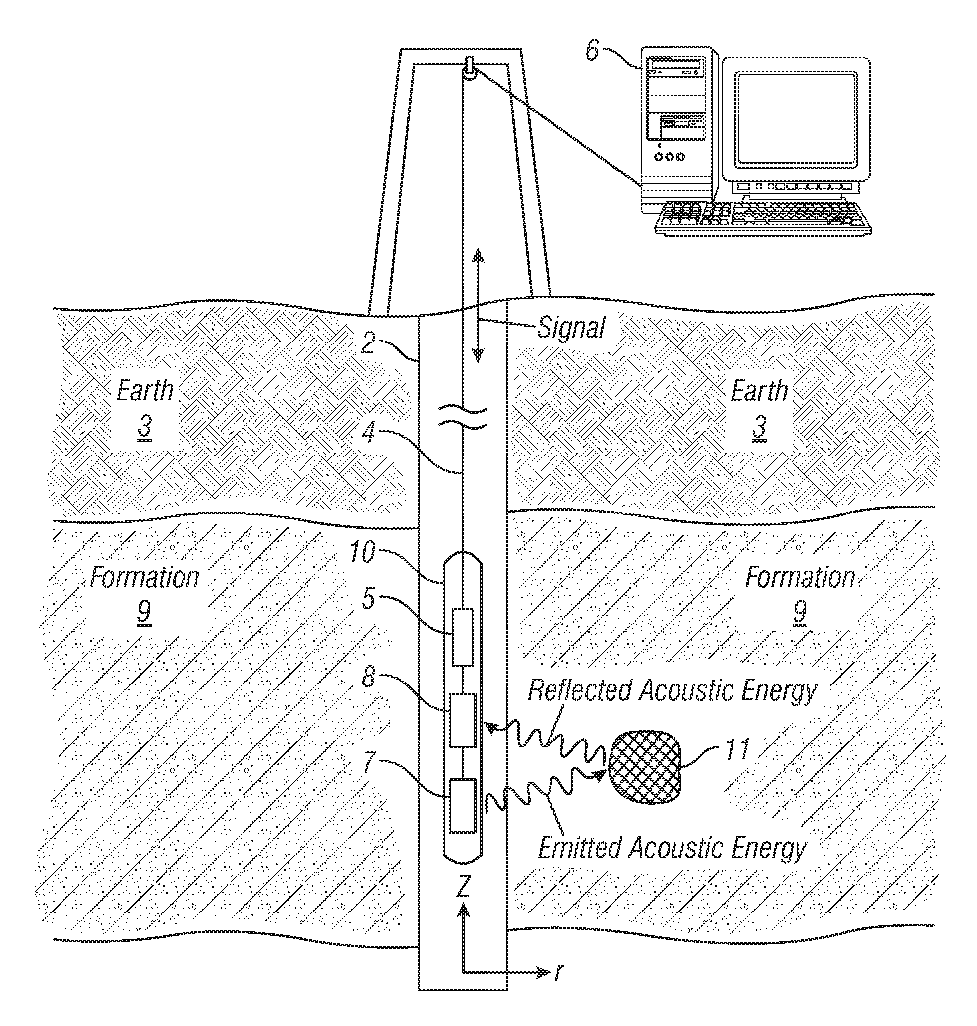
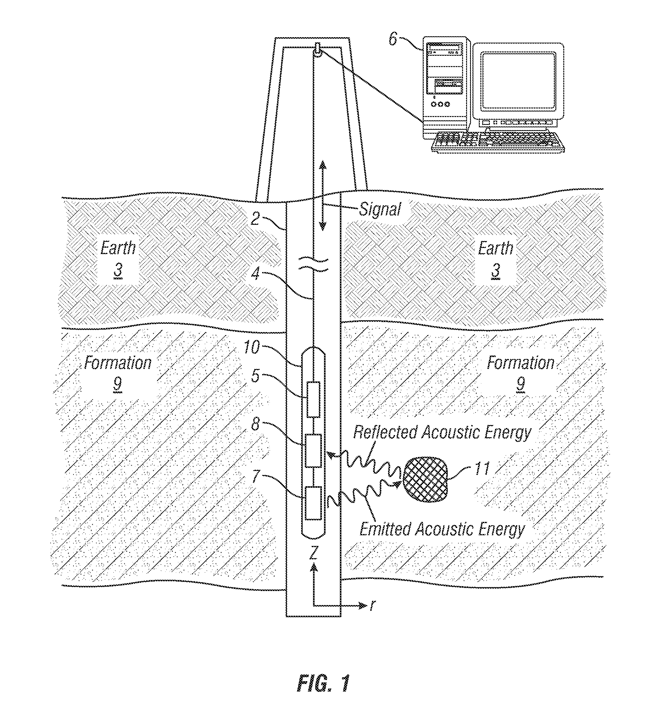
[0016]FIG. 1 illustrates an exemplary embodiment of an acoustic downhole tool 10 disposed in a borehole 2 penetrating the earth 3, which includes an earth formation 9. The earth formation 19 includes any subsurface materials that may be of interest. Included in the earth formation 9 is a subsurface feature 11. The feature 11 has acoustic properties that differ from the surrounding formation 9. Because of the different acoustic properties, the boundary defining the feature 11 can reflect acoustic energy such as acoustic waves.

[0017]The acoustic downhole tool 10 is conveyed through the borehole 2 by a carrier 4. In the embodiment of FIG. 1, the carrier 4 is an armored wireline. Besides supporting the downhole tool 10 in the borehole 2, the wireline can also provide communications between the downhole t...


PUM


Abstract

Disclosed is a method implemented by a processor for imaging a formation penetrated by a borehole. The method includes: obtaining acoustic data in a depth-time domain using an acoustic downhole tool disposed at a depth in the borehole, the acoustic downhole tool having an acoustic source and an acoustic receiver; transforming the acoustic data in the depth-time domain into a Radon domain using a Radon transform; filtering the acoustic data in the Radon domain to increase a signal of interest in the acoustic data in the Radon domain; determining a location of a point in the formation that reflected acoustic energy emitted from the acoustic source to the acoustic receiver, the location of the point being represented in the Radon domain; and inverting the location of the point represented in the Radon domain into a radius-depth domain to image the formation.

Description

CROSS REFERENCE TO RELATED APPLICATIONS[0001]This application claims the benefit of U.S. Application No. 61 / 385,062, filed on Sep. 21, 2010, which is incorporated herein by reference in its entirety.BACKGROUND[0002]1. Field of the Invention[0003]The invention disclosed herein relates to imaging a geologic formation with an acoustic logging tool.[0004]2. Description of the Related Art[0005]Geologic formations are of interest for a variety of reasons such as hydrocarbon production, geothermal production, and carbon dioxide sequestration. One way to obtain information about geologic formations is by using an acoustic logging tool.[0006]The acoustic logging tool is conveyed through a borehole penetrating the earth. The tool emits acoustic energy into a formation and receives acoustic energy that is reflected by the formation back to the tool. With knowledge about the emitted acoustic energy and the reflected acoustic energy, properties of the formation can be estimated. Several factors ...

Claims


Application Information

Patent Timeline
IPC IPC(8): G06F19/00G01V1/36G01V1/48G01V1/32
CPCE21B47/0002E21B47/101G01V1/28G01V2210/51G01V2210/244G01V2210/46G01V2210/40E21B47/002E21B47/107E21B47/00G01V1/44G01V1/48G16Z99/00G01V1/36
Inventor BOLSHAKOV, ALEXEITANG, XIAO MINGPATTERSON, DOUGLAS J.DUBINSKY, VLADIMIRDUBINSKY, ZAREMA
Owner BAKER HUGHES INC
Why Eureka
Try Eureka