Thermoelectric Converter and System Comprising a Thermoelectric Converter

a technology of thermoelectric converter and thermoelectric converter, which is applied in the direction of generator/motor, electrical apparatus, cooling/ventilation/heating modification, etc., can solve the problem of inefficient use of waste heat, and achieve the effect of improving efficiency

Inactive Publication Date: 2012-05-10
IBM CORP
View PDF4 Cites 14 Cited by
  • Summary
  • Abstract
  • Description
  • Claims
  • Application Information

AI Technical Summary

Benefits of technology

[0005]It is an object of the invention to provide a thermoelectric converter with an improved efficiency.

Problems solved by technology

However, while a demand for hot water generally fluctuates strongly during the day, the supply of hot water from a server farm remains constant, making such a use of waste heat inefficient.

Method used


Image

  • Thermoelectric Converter and System Comprising a Thermoelectric Converter
  • Thermoelectric Converter and System Comprising a Thermoelectric Converter
  • Thermoelectric Converter and System Comprising a Thermoelectric Converter

Examples


Embodiment Construction

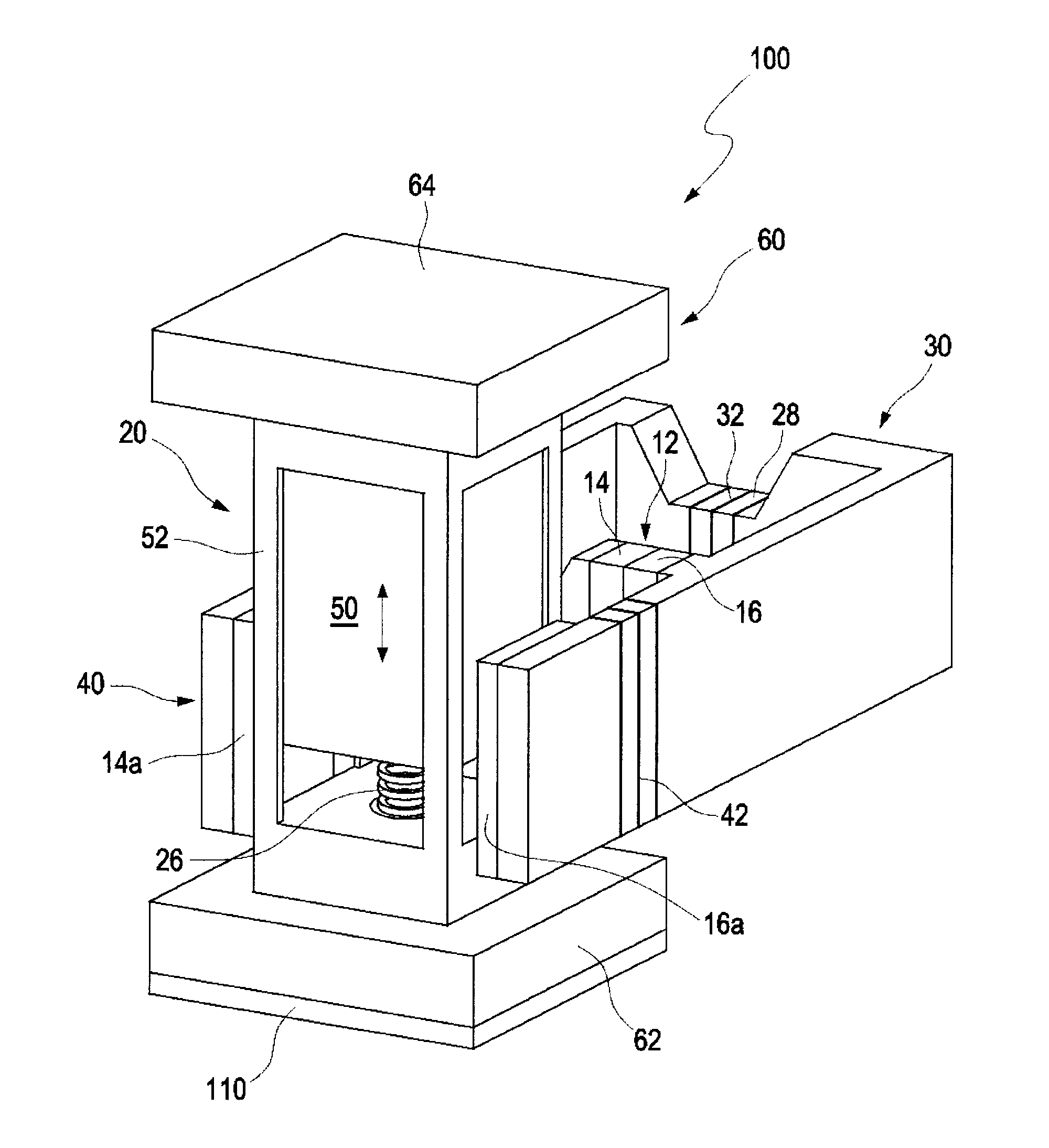
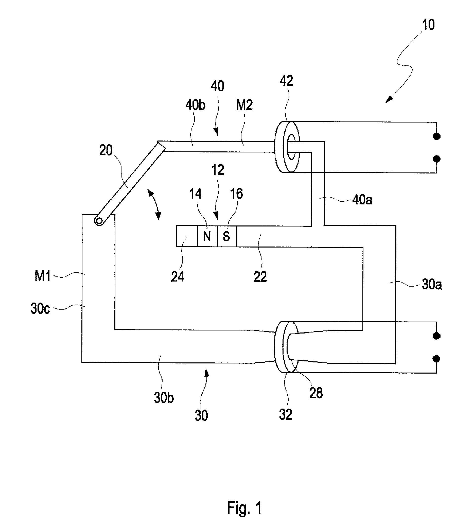
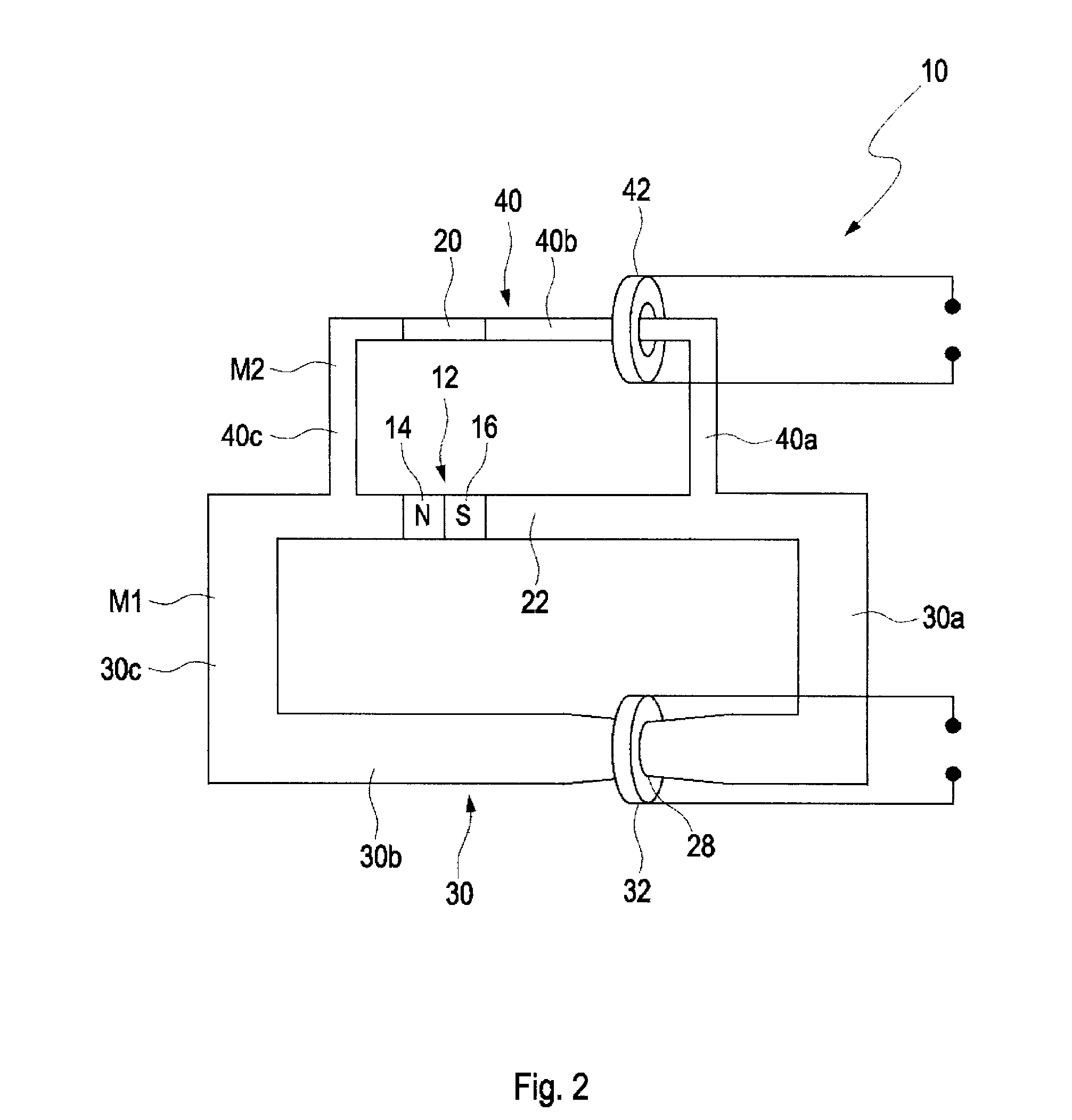
[0045]FIG. 1 illustrates the working principle of a thermoelectric converter 10. The thermoelectric converter 10 converts thermal energy into electric energy.

[0046]The thermoelectric converter 10 comprises a magnet 12 with a first magnetic pole 14 (e.g. a north pole) and a second magnetic pole 16 (e.g. a south pole) and a magnetic switch 20 for closing either a first magnetic circuit M1 or a second magnetic circuit M2. The magnet 12 is arranged in a ferromagnetic leg 22 which is arranged parallel to a first ferromagnetic bridge 30 and a second ferromagnetic bridge 40.

[0047]The first ferromagnetic bridge 30 and the ferromagnetic leg 22 constitute the first magnetic circuit M1. The first ferromagnetic bridge 30 comprises ferromagnetic legs 30a, 30b and 30c wherein ferromagnetic legs 30a and 30c are contacting the ferromagnetic leg 22. A constriction 28 is arranged in the ferromagnetic leg 30b. The magnetic switch 20 is permanently in contact with the ferromagnetic leg 30c and can swit...


PUM


Abstract

An apparatus and process are disclosed that relates to a thermoelectric converter for converting thermal energy into electric energy. The apparatus includes at least one magnetic circuit including magnetic flux; at least one electric coil coupled to the at least one magnetic circuit; a magnetic switch coupled to the at least one magnetic circuit which loads the at least one electric coil with magnetic flux of the at least one magnetic circuit depending on a temperature of the magnetic switch, wherein the magnetic switch has a ferromagnetic state below a critical temperature (Tc) and a paramagnetic state above the critical temperature (Tc).

Description

FIELD OF THE INVENTION[0001]The invention relates to a thermoelectric converter and a system comprising a thermoelectric converter.BACKGROUND OF THE INVENTION[0002]Water-cooled server farms produce waste heat in the range of MW as hot water at a substantially constant temperature level of about 80° C. The hot water can be used for heating purposes or as service water for industrial or domestic use. However, while a demand for hot water generally fluctuates strongly during the day, the supply of hot water from a server farm remains constant, making such a use of waste heat inefficient.[0003]Converting the thermal energy of the waste heat in mechanical energy, e.g. by driving a steam turbine, requires high temperatures of several hundred degrees Celsius.[0004]It is well known in the art to use waste heat for generation of electric energy. For instance, RU 2 379 820 C1 describes a thermoelectric converter employing a permalloy composition having a Curie temperature Tc of e.g. 70° C. Ab...

Claims


Application Information

Patent Timeline
Patent Type & Authority Applications(United States)
IPC IPC(8): H05K7/20H02N11/00
CPCH05K7/20H02N11/00H02N10/00H02N3/00
Inventor GOETTERT, CARSTENHUELS, HARALDKRAEMER, HANS-GUENTERRIES, MANFREDSCHAEFER, ROLF
Owner IBM CORP
Why Eureka
Try Eureka