Switching power supply device

a power supply device and power supply technology, applied in the direction of electric variable regulation, process and machine control, instruments, etc., can solve the problems of overshoot or undershoot of the voltage vfb of the fb terminal, burst power increase, power consumption decrease, etc., to achieve low abnormal noise, low consumption power, and high balance

Active Publication Date: 2012-05-10
FUJI ELECTRIC CO LTD
View PDF4 Cites 38 Cited by
  • Summary
  • Abstract
  • Description
  • Claims
  • Application Information

AI Technical Summary

Benefits of technology

[0045]According to the present invention, burst power, a burst frequency, and an output ripple can be designed with a high balance over an entire input voltage range, at the time of a burst operation. Therefore, a switching power supply device that has low consumption power, a low abnormal noise, and a low output ripple can be realized.

Problems solved by technology

In addition, overshoot or undershoot is generated in the voltage Vfb of the FB terminal due to switching.
Meanwhile, in the switching power supply device that is disclosed in Japanese Patent Application Laid-Open (JP-A) No. 2008-245419, when the burst threshold voltage Vth increases, the burst power increases and hence the consumption of power decreases.
Conversely, when the burst threshold voltage Vth decreases, the burst power decreases and hence the consumption of power increases.
In the switching power supply device, when the switching power supply device operates in the burst mode, because the burst frequency is generally in a range of 200 Hz to 2 kHz which is a frequency range in the audible zone, an abnormal noise by a magnetostrictive sound from the transformer T10 will cause a problem.
That is, when the input voltage is high, because the burst power Pburst is large and the burst frequency Fburst is high, the abnormal noise level Paud becomes high.
For this reason, in the switching power supply device, it is difficult to realize low consumption of power, a low abnormal noise, and a low output ripple over an entire input voltage range at the time of the burst operation.
In addition, in the switching power supply device that is described in JP-A No. 2006-149104, it is difficult to realize low consumption of power, a low abnormal noise, and a low output ripple over an entire input voltage range, due to the structure thereof.

Method used


Image

  • Switching power supply device
  • Switching power supply device
  • Switching power supply device

Examples


Embodiment Construction

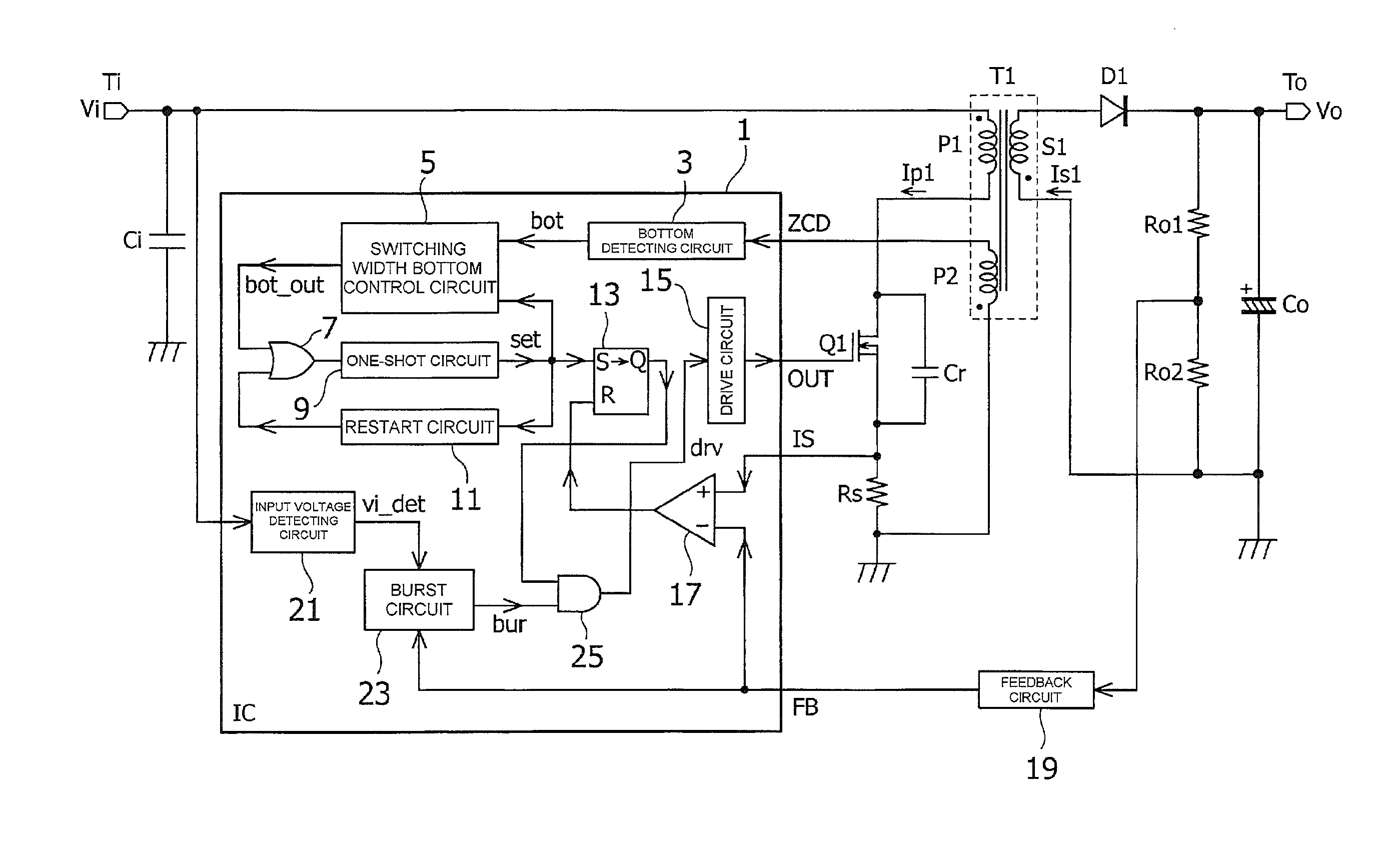
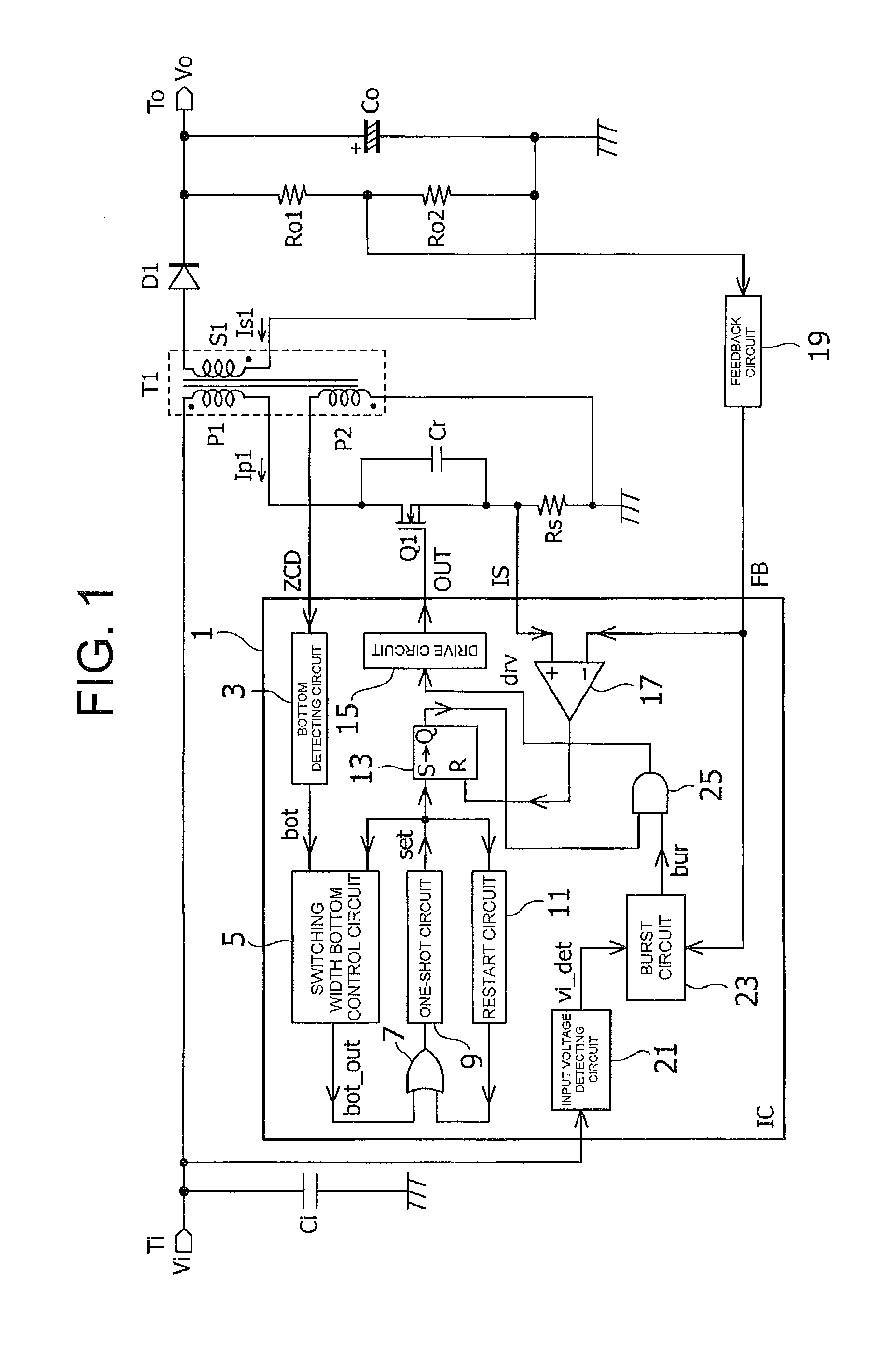
[0062]FIG. 1 is a circuit diagram illustrating a switching power supply device according to an embodiment of the present invention that has the configuration as a pseudo resonance converter.

[0063]In the switching power supply device, a transformer T1 includes a primary winding P1, a secondary winding S1, and an auxiliary winding P2. One end of the primary winding P1 is connected to an input terminal Ti and the other end thereof is connected to a drain of a MOSFET which is a switching element Q1. One end of the secondary winding S1 is connected to an output terminal To through a diode D1 and the other end thereof is connected to a ground point. One end of the auxiliary winding P2 is connected to a ZCD terminal to be an input terminal for zero current detection in a switching control circuit 1, to be described below, and the other end thereof is connected to a ground point.

[0064]A smoothing capacitor Ci is connected between the input terminal Ti and the ground point, a smoothing capac...


PUM


Abstract

A switching power supply device that includes a feedback terminal to which a feedback signal according to a load state is input, and a comparator which compares a terminal voltage of the feedback terminal with a reference voltage and determines whether the load state is a normal load state or a light load state. The switching power supply device also includes pull-up resistors which are connected to the feedback terminal, a switch element which switches resistance values of the pull-up resistors according to the change of the load state, and a switch element which switches the resistance values of the pull-up resistors according to whether the input voltage is high or low.

Description

CROSS REFERENCE TO RELATED APPLICATION[0001]The entire disclosure of the inventor's corresponding Japanese patent application, Serial No. JP PA 2010-250846, filed Nov. 9, 2010, is hereby incorporated by reference.BACKGROUND OF THE INVENTION[0002]1. Field of the Invention[0003]The present invention relates to a switching power supply device which includes a light load intermittent oscillation (burst mode) handling circuit.[0004]2. Description of the Related Art[0005]In a switching power supply device, since a switching loss becomes noticeable at the time of a light load, particularly, during standby mode, it is effective to decrease the number of switching operations per second to decrease the consumption of power. Therefore, a control system that is called an intermittent oscillation (burst mode) is preferably used as a means for decreasing the number of switching operations.[0006]FIG. 13 illustrates the configuration of a switching power supply device adopting a burst mode control ...

Claims


Application Information

Patent Timeline
Patent Type & Authority Applications(United States)
IPC IPC(8): H02M3/335
CPCH02M3/33523Y02B70/16H02M2001/0035H02M2001/0022H02M1/0022H02M1/0035Y02B70/10
Inventor CHEN, JIANYAMADAYA, MASAYUKI
Owner FUJI ELECTRIC CO LTD
Why Eureka
Try Eureka