
Engineered Aerosol Particles, And Associated Methods

a technology of aerosol particles and aerosol granules, applied in the field of engineered particles, can solve the problems of particle design without rifling or autorotation, and achieve the effect of increasing the settling time of the fabricated nanoparticle body member

Inactive Publication Date: 2012-05-10
LIQUIDIA TECH +1
View PDF1 Cites 14 Cited by
  • Summary
  • Abstract
  • Description
  • Claims
  • Application Information

AI Technical Summary

Benefits of technology

[0010]In the therapeutic context, control over the size and shape of particles may enable the particles to be used to access different regions of the pulmonary system upon delivery via inhalation or nasal delivery. In certain embodiments, the sizes of the nanoparticles may be specifically engineered to afford delivery to particular sites within the lung. In certain embodiments, the shapes of the nanoparticles may be engineered such that the particles undergo autorotation and / or tumbling to change the flight characteristics of the particles, opening up opportunities to access various locations within the lung. In some embodiments, multiple sizes and / or shapes of particles may be combined to produce one composition that provides for delivery of particles of different sizes and / or shapes to various sites within the lung. For example, a composition combining particles of different sizes may be designed to deposit certain larger particles in the mouth and the first few generations of airways as well as certain larger particles in the deep lung and the alveolar region.
[0012]Another aspect provides a method of delivering an engineered aerosol nanoparticle. Such a method comprises providing in aerosol form a plurality of nanoparticle body members being non-spherical. Each nanoparticle body member is configured to provide at least one of auto-rotation, tumbling, or lift when entrained in an airstream, which could increase settling time of the fabricated nanoparticle body member. The method further comprises releasing the nanoparticle body members into an airstream.
[0013]Still yet another aspect provides a method of fabricating a nanoparticle for use in aerosol applications. The method comprises providing a patterned template and a substrate, wherein the patterned template comprises a patterned template surface having a plurality of recessed areas formed therein. The method further comprises disposing a volume of liquid material in or on the patterned template surface and / or the plurality of recessed areas. The method further comprises forming one or more particles by: (a) contacting the patterned template surface with the substrate and treating the liquid material; and / or (b) treating the liquid material. Each formed particle is non-spherical and is configured to provide at least one of auto-rotation, tumbling, or lift when entrained in an airstream, which could increase settling time of the fabricated nanoparticle body member.

Problems solved by technology

Further, particles have not been designed with rifling or autorotation to generate a leading edge vortex and lift for providing improved aerodynamic characteristics of the particles.

Method used


Image

  • Engineered Aerosol Particles, And Associated Methods
  • Engineered Aerosol Particles, And Associated Methods
  • Engineered Aerosol Particles, And Associated Methods

Examples


example 1

Design of Novel Shapes for Engineered Aerosols

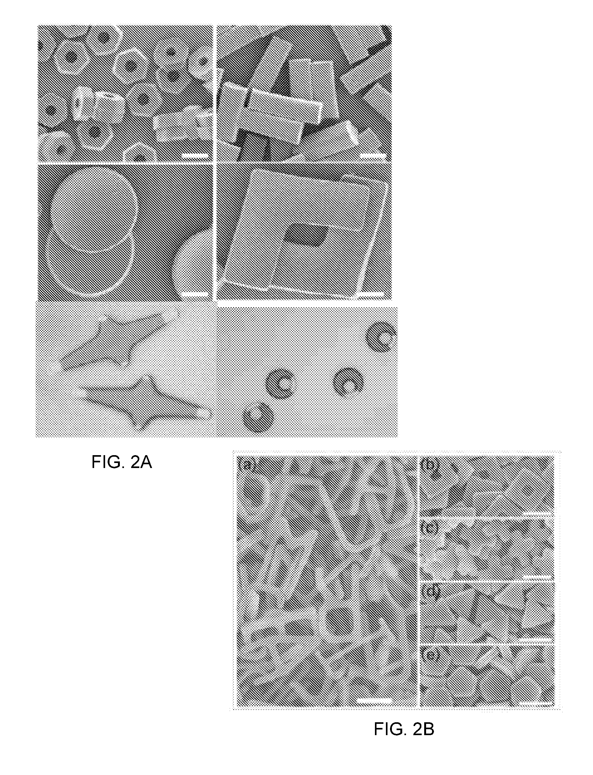
[0105]The uniqueness of shaped aerosols as related to PRINT® is its ability to adapt naturally occurring shapes as well as to design novel artificial (or engineered) shapes in order to facilitate enhanced and potentially tunable flight characteristics. This is a key distinction of PRINT® aerosols over that of the standard spherical shapes approximated by most commercially available aerosols. According to one embodiment, design parameters which influence aerodynamic properties include shapes that are:[0106]i. non-spherical;[0107]ii. symmetrical and promote autorotation about a central axis;[0108]iii. asymmetrical and promote tumbling because of an unbalanced center of gravity (CG);[0109]iv. capable of potentially generating lift by inducing leading edge vortices in addition to autorotation or tumbling;[0110]v. fenestrated or that include cavities creating unbalanced CGs and thereby inducing autorotation, tumbling, and / or leading-edge vort...

example 2

Microfabricated Templates for Engineered Aerosols

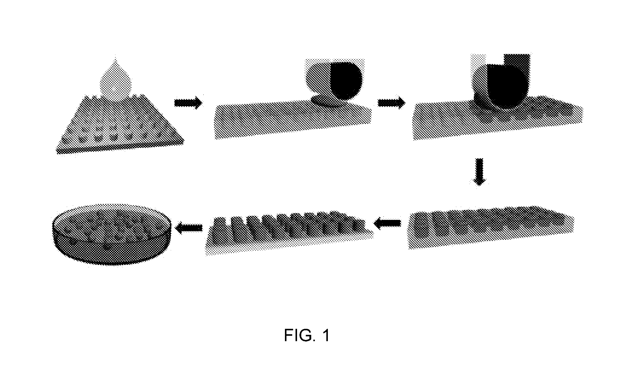
[0116]Microfabricated templates processed using traditional lithography techniques form the basis of shaped PRINT® aerosols. Master templates for solid shapes were fabricated by exposing SU-8 negative resist (Microchem Corp, Newton, Mass.) to a 365 nm photolithography process on an I-line stepper. High aspect ratio features with fenestrations were resolved using a deep UV (193 nm) scanner (ASML, The Netherlands) on NFR 90 negative resist (JSR Micro Inc, Sunnyvale, Calif.). FIG. 20 illustrates SEM images of microfabricated templates for PRINT® aerosols, wherein: (A) Lollipop; (B) L-Dumbbell; (C) V-Boomerang; (D) Helicopter; (E) Solid Lorenz; (F) Fenestrated Lorenz; (G) Solid Ellipsoid; (H) Fenestrated Ellipsoid.

[0117]Rolls of thin molds were then produced from these master templates using a proprietary technique developed by Liquidia Technologies (RTP Durham, N.C.). These molds allow for the roll-to-roll production of shaped aerosols. ...

example 3

Fabrication of Engineered Aerosols

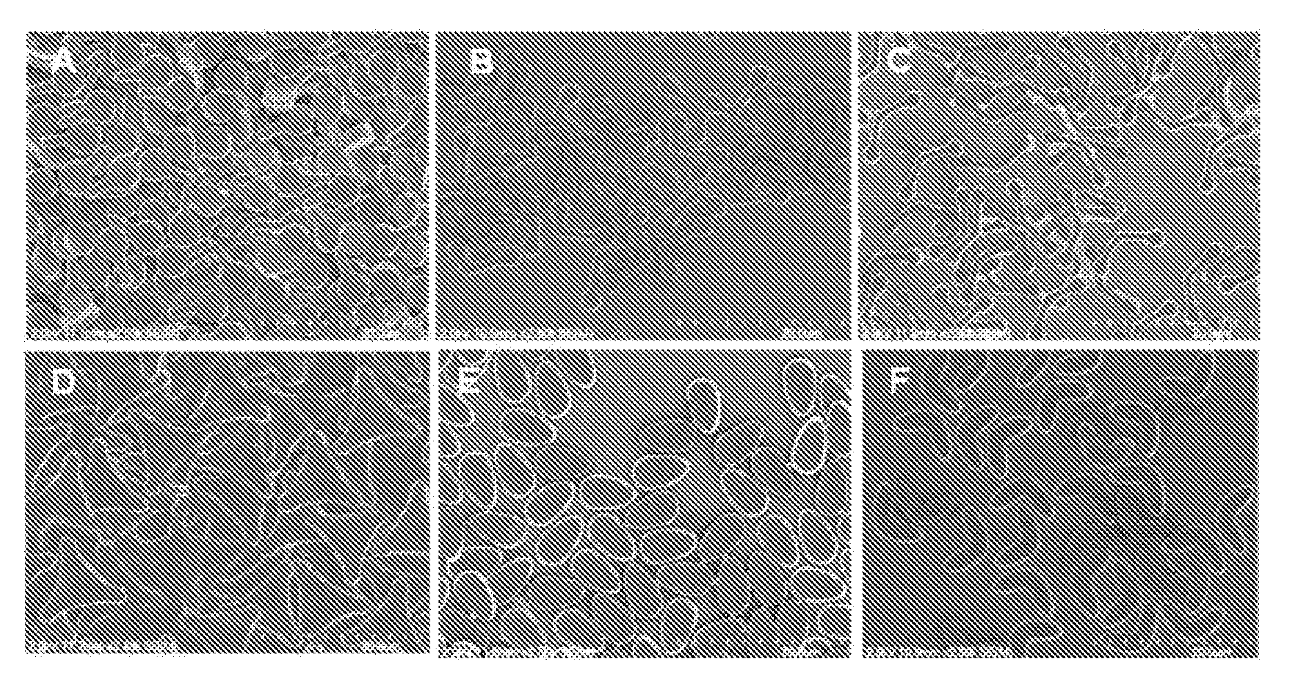
[0118]The PRINT® process enables the fabrication of micron-sized aerosols. To demonstrate proof-of-concept, 7 different shapes were fabricated from a photocurable PEG hydrogel matrix as shown in FIG. 21. FIG. 21 shows Optical images (A-F) (100×) and SEM (inserts) images (2500×) of shaped PRINT® aerosols, wherein: (A) Lollipops; (B) V-Boomerangs; (C) L-Dumbells; (D) Pollen; (E) Ellipsoids; (F) Helicopters; (G) Lorenz; (H) Mixed.

[0119]While the method of filling and photocuring this monomer in the molds has been previously demonstrated, a novel method of harvesting these aerosols to a PVOH sacrificial harvest layer (under specific temperature and pressure conditions) was developed. Furthermore, the incorporation of fluorescent dye cargo in these particles demonstrates the ability to use the particles as delivery vehicles for other diagnostic and therapeutic agents.

Goal B: Evaluate Aerosol Characteristics


PUM

PropertyMeasurementUnit
length scaleaaaaaaaaaa
particle sizeaaaaaaaaaa
lengthaaaaaaaaaa

Abstract

An engineered aerosol particle for use in aerosol applications is provided. The engineered aerosol particle comprises a fabricated nanoparticle body member being non-spherical. The fabricated nanoparticle body member is configured to provide at least one of auto-rotation, tumbling, or lift when entrained in an airstream to thereby increase settling time of the fabricated nanoparticle body member. An associated method is also provided.

Description

FIELD OF THE INVENTION[0001]Embodiments of the present disclosure relate to engineered particles, and more particularly, to engineered aerosol particles and methods associated therewith.BACKGROUND OF THE INVENTION[0002]Particles have been a key component for tens of thousands of products in many different industries. However, up to this point, these particles have, for the most part, been polydisperse in size and shape, with shapes that range from spherical in nature to granulated or globular in shape due to the milled or spray drying processes used to create the particles. In general, particle engineering has not typically included control of size and shape of the engineered particles. Particles for many products, especially for inhaled pharmaceuticals, are intrinsically polydisperse in size and shape due to the milling or spray drying processes used to create the particles. Further, particles have not been designed with rifling or autorotation to generate a leading edge vortex and...

Claims


Application Information

Patent Timeline
Patent Type & Authority Applications(United States)
IPC IPC(8): A61K51/00C08G63/08B05B15/00C08G65/08B32B5/16B82Y5/00B82Y30/00
CPCY10T428/2982B01J2/22
Inventor DESIMONE, PHILIPMAYNOR, BENJAMINNAPIER, MARYPILLAI, JONATHANDESIMONE, JOSEPH M.PATRICK, WILLLAAKER, KYLEZHANG, HANJUN
Owner LIQUIDIA TECH
Learn More