Sewage Suction Device

a sewage suction device and a technology for sewage, which are applied in the direction of sewage draining, machines/engines, engines without rotary main shafts, etc., can solve the problems of large amount of water required for the siphon phenomenon, limited installation location and operation space, and complex structure, etc., to reduce the stroke of the piston without reducing its efficiency, compact structure, and convenient operation

Inactive Publication Date: 2012-05-17
GU GUOQING
View PDF1 Cites 3 Cited by
  • Summary
  • Abstract
  • Description
  • Claims
  • Application Information

AI Technical Summary

Benefits of technology

[0003]The purpose of the current invention is to replace the inadequacies that are present in the existing technology of the sewerage-pumping device. This invention utilizes the two-stage movement of a piston and a cylinder liner and greatly reduces the piston stroke without reducing its efficiency. Its advantages include compact structure, convenient operation and high efficiency.
[0021]The invention utilizes the two-stage movement of the piston and the cylinder liner. The first stage comprises the working stroke, in which the piston is in motion and the cylinder liner is stationary. This leads to the formation of negative pressure inside the cylinder liner that is located at the end of the toilet siphon, which in turn forces water to start a rapid siphon in the pipeline and therefore completes the pumping. The second stage does not increase working stroke. At this stage the cylinder liner is active and the piston is stationary. The cylinder liner moves along the piston rod that is located inside the cylinder sleeve, and therefore opens the waste-discharging outlet on the cylinder sleeve. This allows the waste to be discharged through the sewer pipe. Consequently, the device greatly reduces the piston stroke without reducing its efficiency. The advantages of the current invention include compact structure, convenient operation and high efficiency.

Problems solved by technology

However, this siphon phenomenon requires a large amount of water to ensure proper drainage.
Due to the size limitation of the toilet itself, the installation location and the operational space are limited.
This design in turn results in defects such as complexity in structure, difficulty in operation, and low efficiency, etc., and hence restricting the technology and general application of such “suction-type water-saving toilet”.

Method used


Image

  • Sewage Suction Device
  • Sewage Suction Device
  • Sewage Suction Device

Examples


Embodiment Construction

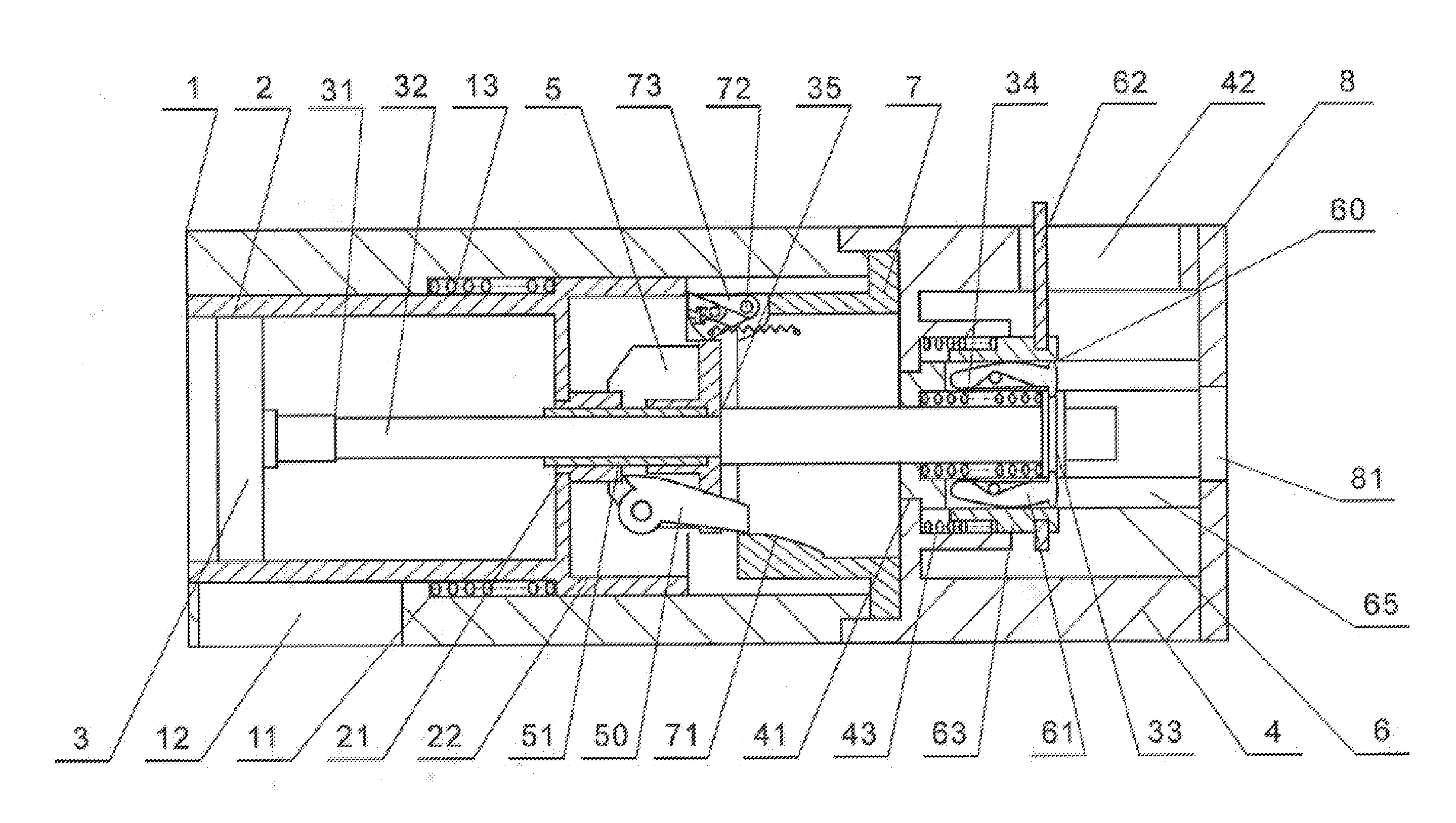
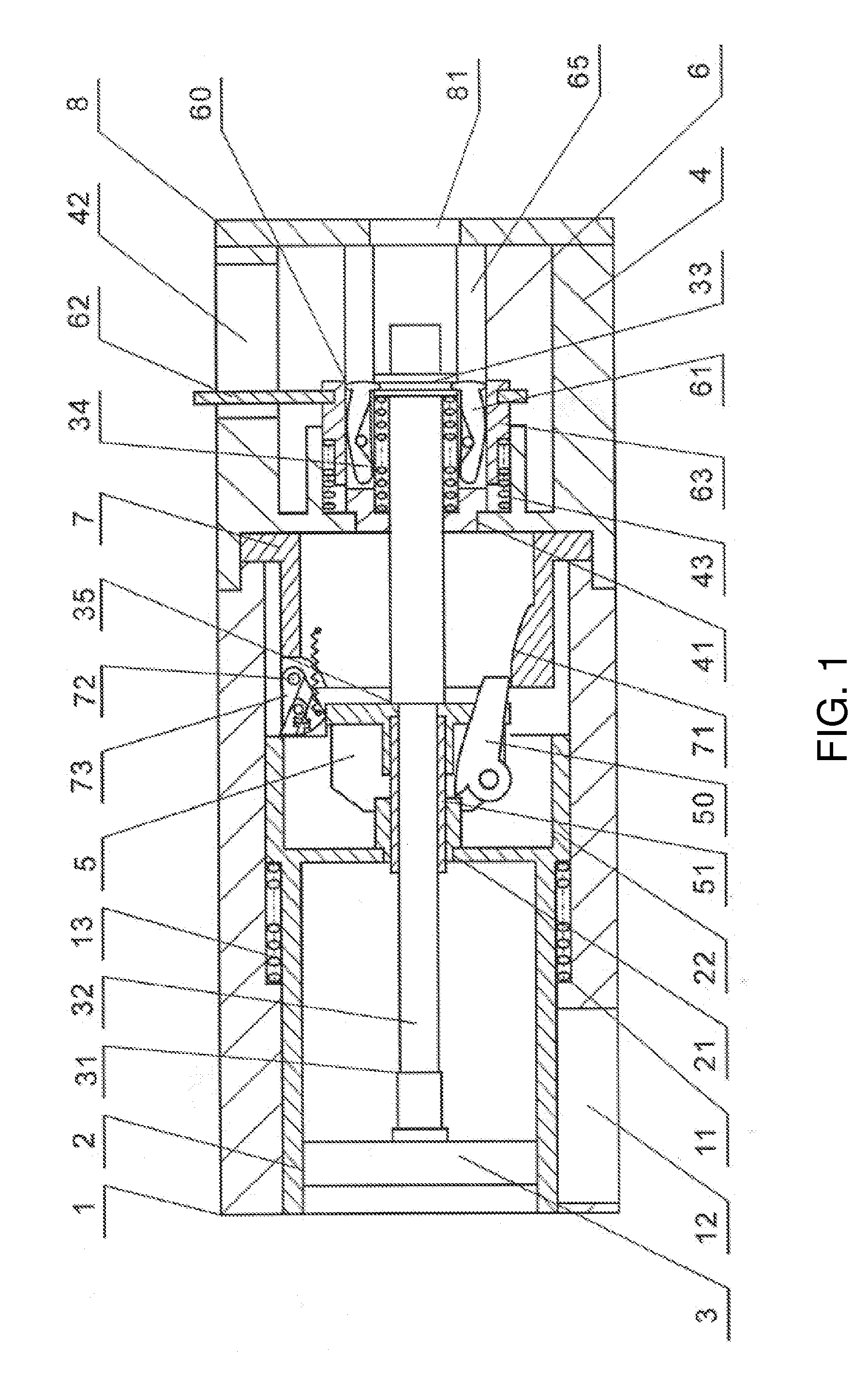
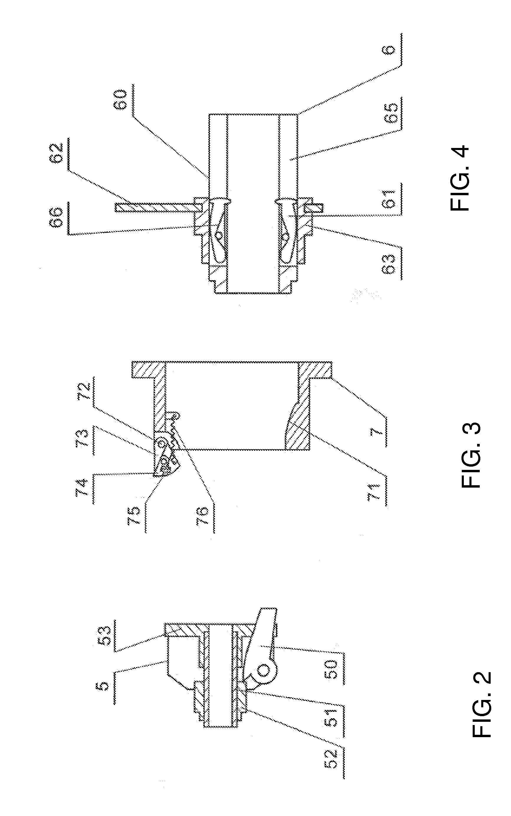
[0026]See FIG. 1, the invention includes:[0027]A cylindrical sleeve (1) where an inside of the sleeve includes a stepped hole (11);[0028]a wall of the sleeve includes a waste-discharging outlet (12);[0029]A cylinder liner with a bottom (2) that includes a shaft hole (21); the cylinder wall of the cylinder liner is provided with a flange (22);[0030]A piston (3) with a piston rod (32);[0031]A cylinder sleeve cover (4) with a stepped hole (41) along its axis; the body of the cylinder sleeve cover is also provided with a hanging hole (42);[0032]A cylinder liner lock (5) that clutches the piston rod (32);[0033]A shifting fork assembly (6) that is fixed inside the stepped hole (41) of the cylinder cover (4);[0034]A ring shaped cylinder liner lock seat (7) is provided with a slope (71) and a pivot pin (72);[0035]An annular end cover (8) is provided with a through hole (81) in its center;

[0036]Wherein: the cylinder liner with a bottom (2) is located inside the cylinder sleeve (1), the pisto...


PUM


Abstract

The invention discloses a suction drainage device that comprises: a cylinder sleeve where the inside of the cylinder sleeve is provided with a step hole and the wall of the cylinder sleeve has a waste-discharging outlet; a cylinder liner with a bottom that includes a shaft hole and where the wall of the cylinder liner is provided with a flange; a piston with a piston rod; a cylinder sleeve cover with a step hole along the axis, and the body is also provided with a hanging hole; a cylinder liner lock that clutches the piston rod; a shifting fork assembly that is fixed inside the step hole of the cylinder sleeve cover; a ring shaped cylindrical liner lock seat that includes a slope and a pivot pin; an annular end cover that contains a through hole in its center, wherein: the cylinder liner is located inside the cylinder sleeve, the piston is located inside the cylinder liner; the cylinder sleeve cover is connected to the cylinder sleeve along the axis; the cylinder liner lock seat is located in between the cylinder sleeve and cylinder sleeve cover; the annular end cover caps the cylinder sleeve cover. The invention utilizes the two-stage movement of the piston and the cylinder liner, which greatly reduces the piston stroke without reducing its efficiency. Its advantages include compact structure, convenient operation and high efficiency.

Description

FIELD OF INVENTION[0001]This invention relates to the field of sanitary technology. In particular this invention relates to a device that strengthens the sewage pumping system implemented on a toilet.TECHNOLOGY BACKGROUND[0002]The application of the siphon principle on a toilet to strengthen sewage suction is widely used. Under atmospheric pressure, the release of water from the water tank generates the siphon phenomenon that increases the efficiency of drainage. However, this siphon phenomenon requires a large amount of water to ensure proper drainage. In order to reduce water consumption, Chinese Patent Application No. 200410022242.7 discloses a suction-type water-saving toilet. The structure includes a piston tube at the end of the toilet siphon tube. The piston movement within the piston tube creates negative pressure at the end of the siphon tube. This causes the water in the pipeline to siphon rapidly, thereby decreasing water consumption. Due to the size limitation of the toi...

Claims


Application Information

Patent Timeline
Patent Type & Authority Applications(United States)
IPC IPC(8): F16J10/00
CPCE03F1/006E03D5/00
Inventor GU, GUOQING
Owner GU GUOQING
Why Eureka
Try Eureka