
Turbomachine nozzle cowl having patterns with lateral fins for reducing jet noise

a technology of lateral fins and cowls, which is applied in the direction of machines/engines, combustion engines, thin material handling, etc., can solve the problems of degrading the efficiency of the nozzle and the cost of a penalty on the performance of the turbomachine, and achieve the effect of limiting the impact of patterns and reducing the noise of the j

Active Publication Date: 2012-05-17
SN DETUDE & DE CONSTR DE MOTEURS DAVIATION S N E C M A
View PDF4 Cites 3 Cited by
  • Summary
  • Abstract
  • Description
  • Claims
  • Application Information

AI Technical Summary

Benefits of technology

The present invention proposes a new geometrical shape for jet noise reduction patterns in a turbomachine nozzle to further reduce jet noise while limiting the impact on the aerodynamic performance of the nozzle. The shapes of the patterns include a plurality of triangles, with fins inclined radially relative to the patterns to enhance mixing between the streams flowing on either side of the nozzle. The fins are connected to the patterns at the base and at the vertex, creating an opening for the flows of the streams at the outlet from the patterns to limit the drag of the fins and the aerodynamic performance of the nozzle. The shapes of the patterns and fins are designed to optimize the generation of turbulence and mixing between the streams. The invention provides a turbomachine nozzle with improved jet noise reduction and aerodynamic performance.

Problems solved by technology

The sources of noise in a turbomachine are numerous, but it has been observed that the jet noise at the outlet from the nozzle is the noise that predominates during airplane takeoff.
This reduction, which needs to be increased, is nevertheless obtained at the cost of a penalty on the performance of the turbomachine, since the efficiency of the nozzle is degraded.

Method used


Image

  • Turbomachine nozzle cowl having patterns with lateral fins for reducing jet noise
  • Turbomachine nozzle cowl having patterns with lateral fins for reducing jet noise
  • Turbomachine nozzle cowl having patterns with lateral fins for reducing jet noise

Examples


Embodiment Construction

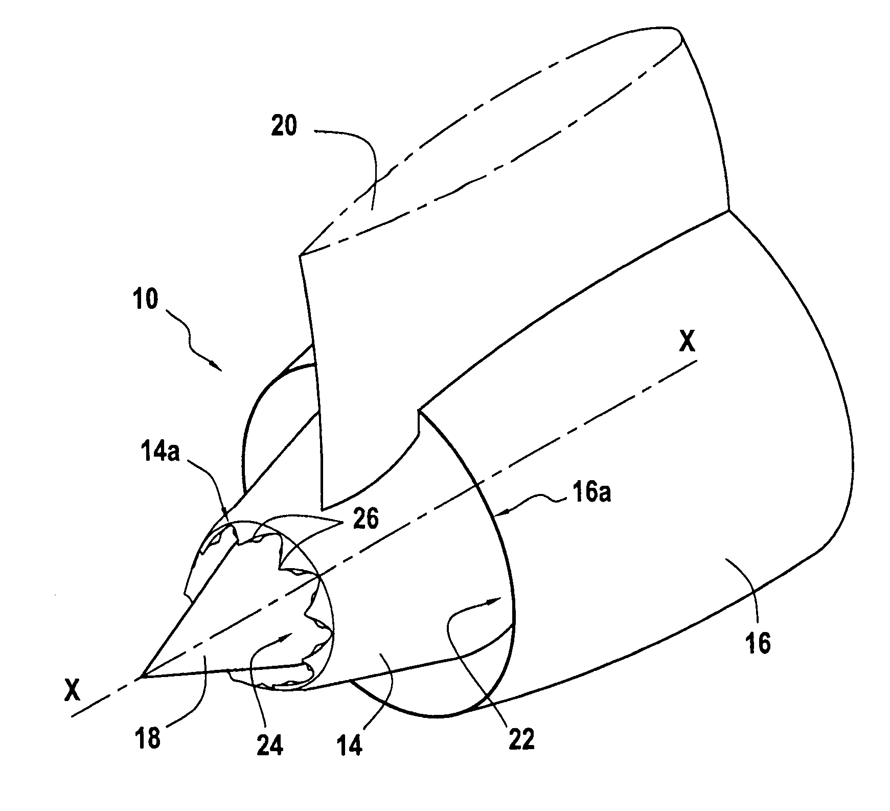
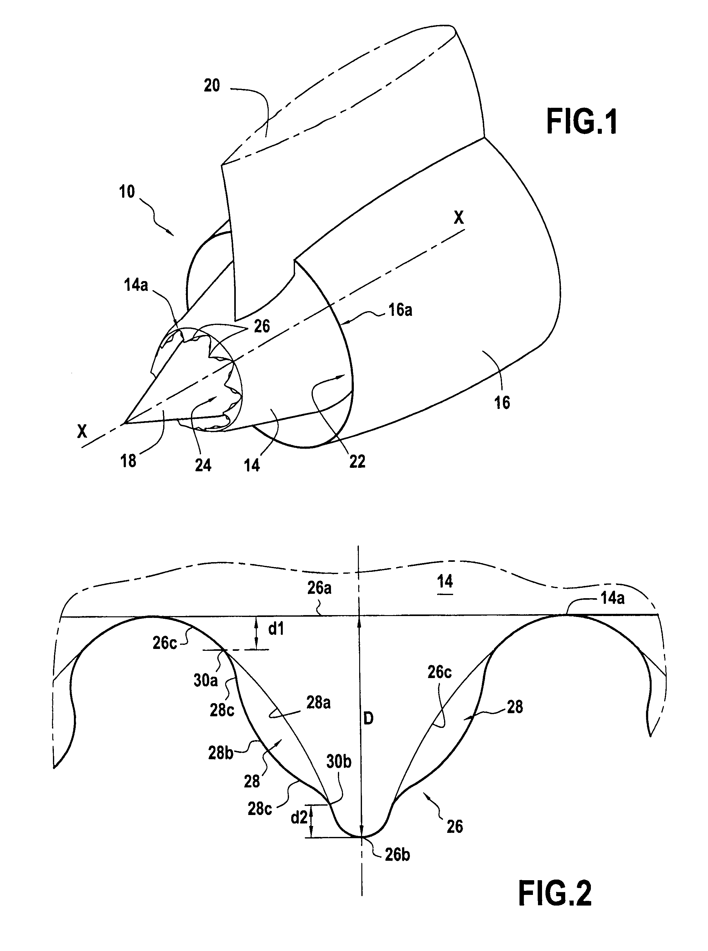
[0023]FIG. 1 is a highly diagrammatic perspective view of a separate-stream nozzle 10 of a turbomachine.

[0024]The nozzle 10 is of axially symmetrical shape about its longitudinal axis X-X and it is typically formed by a primary cowl 14, a secondary cowl 16, and a central body 18, all three of which are centered on the longitudinal axis X-X of the nozzle.

[0025]The primary cowl 14 is substantially cylindrical or frustoconical in shape and it extends along the axis X-X of the nozzle. The central body 18 is arranged concentrically inside the primary cowl 14 and it is terminated by a substantially conical portion.

[0026]The secondary cowl 16 is also substantially cylindrical or frustoconical in shape, it surrounds the primary cowl 14, while being concentric therewith, and it also extends along the longitudinal axis X-X of the nozzle. The primary cowl 14 extends longitudinally downstream beyond the secondary cowl 16.

[0027]It should be observed in the embodiment of FIG. 1 that the central b...


PUM


Abstract

An annular cowl for a turbomachine nozzle, the cowl including a plurality of patterns arranged to extend a trailing edge of the cowl and circumferentially spaced apart from one another. Each pattern has an outline of substantially polygonal shape with a base formed by a portion of the trailing edge of the cowl and at least one vertex that is spaced downstream from the base and that is connected thereto by lateral edges, and in each of its lateral edges, each pattern includes at least one fin, each fin being inclined radially relative to the pattern in a plane that is inclined at an angle lying in the range 0° to 45° relative to a radial direction.

Description

BACKGROUND OF THE INVENTION[0001]The present invention relates to the general field of reducing jet noise at the outlet from a turbomachine nozzle. It relates more particularly to a cowl for a turbomachine nozzle of the separate-stream type that is provided with patterns for reducing jet noise.[0002]Nowadays, sound pollution has become a major concern for engine manufacturers who are being confronted more and more with the acoustic nuisance of their turbomachines. The sources of noise in a turbomachine are numerous, but it has been observed that the jet noise at the outlet from the nozzle is the noise that predominates during airplane takeoff. Since certification authorities are becoming more and more demanding in terms of sound emission from turbomachines, engine manufacturers are being required to reduce the noise from their turbomachines, and in particular to reduce jet noise at the outlet from nozzles.[0003]Typically, a separate-stream nozzle for a turbomachine has a primary cow...

Claims


Application Information

Patent Timeline
Patent Type & Authority Applications(United States)
IPC IPC(8): F02K99/00
CPCF02K1/48F02K1/386Y10T137/0536
Inventor QUARIN, BENEDETTAZEGGAI, KAMEL
Owner SN DETUDE & DE CONSTR DE MOTEURS DAVIATION S N E C M A
Learn More