Electromagnetic, continuously variable transmission power split turbo compound and engine and vehicle comprising such a turbo compound

a technology of continuously variable transmission and turbo compound, which is applied in the direction of machines/engines, electric devices, vehicle sub-unit features, etc., can solve the problems of gear wear, noise, vibration, and substantial cost in terms of system complexity and efficiency, and achieve the effect of reducing the specific fuel consumption of brakes

Inactive Publication Date: 2012-05-17
VOLVO LASTVAGNAR AB
View PDF33 Cites 33 Cited by
  • Summary
  • Abstract
  • Description
  • Claims
  • Application Information

AI Technical Summary

Benefits of technology

[0002]Mechanical turbo compound engines are well known, such as shown in U.S. Pat. No. 4,843,822, and generally include a power turbine placed in the exhaust gas stream, with a mechanical drive coupling through appropriate gear reduction and a fluid or spring coupling, driving the flywheel of the engine. In such turbo compound engines energy is recovered from the exhaust gas strea...

Problems solved by technology

While such a system may provide the advantages of variable turbo compound speed, it is at substantial cost in terms of system complexity and efficie...

Method used


Image

  • Electromagnetic, continuously variable transmission power split turbo compound and engine and vehicle comprising such a turbo compound
  • Electromagnetic, continuously variable transmission power split turbo compound and engine and vehicle comprising such a turbo compound
  • Electromagnetic, continuously variable transmission power split turbo compound and engine and vehicle comprising such a turbo compound

Examples


Embodiment Construction

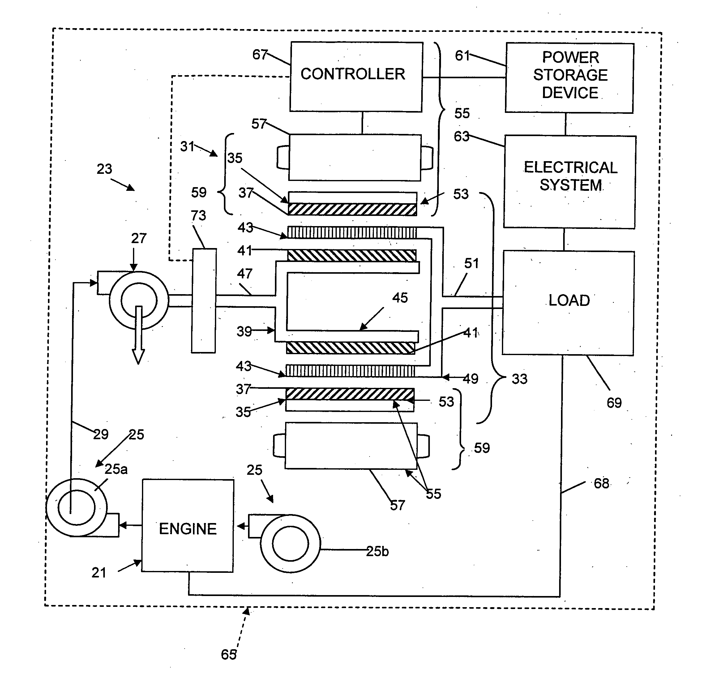
[0017]An internal combustion engine 21 comprising an electromagnetic, CVT power split turbo compound 23 is shown in FIG. 1. The engine 21 comprises a turbocharger 25 including a turbocharger turbine 25a and a turbocharger compressor 25b. However, the turbocharger 25 is optional. The turbo compound 23 comprises a power recovery turbine 27 (hereinafter “turbine”, “turbo compound turbine” or the like) driven by exhaust gases from the engine 21. An exhaust conduit 29 connects the turbine 27 to the engine 21.

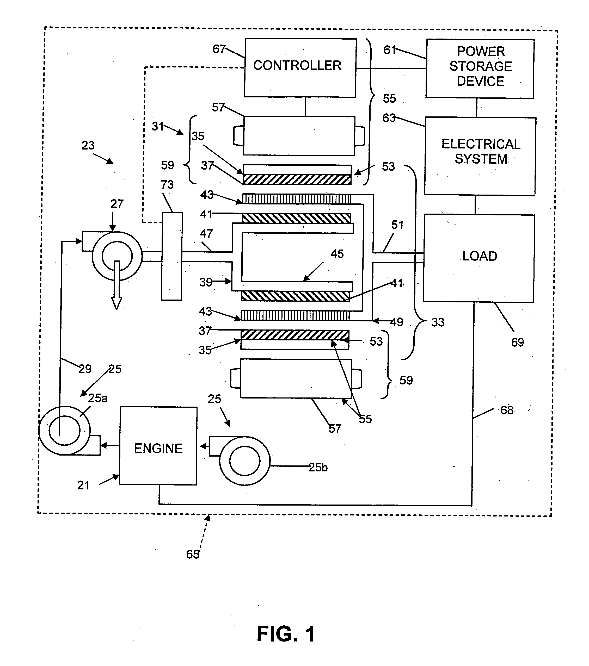
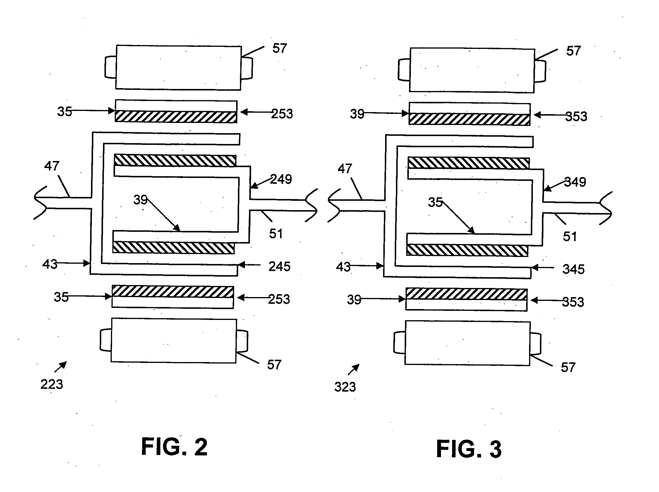
[0018]The turbo compound 23 further comprises a power split device 31 (PSD) comprising a magnetic gear arrangement 33. The magnetic gear arrangement 33 comprises a high speed rotor 35 (HSR) comprising a first quantity of permanent magnets 37, a low speed rotor 39 (LSR) comprising a second quantity of permanent magnets 41, and a plural pole rotor 43 (PPR) between the high speed rotor and the low speed rotor. The PPR 43 will ordinarily be designed to minimize eddy currents, such as by ...


PUM


Abstract

An electromagnetic, continuously variable transmission power split turbo compound includes a turbo compound turbine driven by exhaust gases from an internal combustion engine, and a power split device comprising a magnetic gear arrangement. The magnetic gear arrangement includes a high speed rotor comprising a first quantity of permanent magnets, a low speed rotor comprising a second quantity of permanent magnets, and a plural pole rotor between the high speed rotor and the low speed rotor. A first rotor of the high speed rotor, the low speed rotor, and the plural pole rotor includes a mechanical input drive adapted to be driven by the turbine. A second rotor of the high speed rotor, the low speed rotor, and the plural pole rotor includes a mechanical output drive. A third rotor of the high speed rotor, the low speed rotor, and the plural pole rotor is unconnected to a mechanical drive and includes a controlling rotor for controlling a ratio of input drive angular velocity to output drive angular velocity.

Description

BACKGROUND AND SUMMARY[0001]The present invention relates generally to turbo compounds and, more specifically, to an electromagnetic, continuously variable transmission (CVT) power split turbo compound.[0002]Mechanical turbo compound engines are well known, such as shown in U.S. Pat. No. 4,843,822, and generally include a power turbine placed in the exhaust gas stream, with a mechanical drive coupling through appropriate gear reduction and a fluid or spring coupling, driving the flywheel of the engine. In such turbo compound engines energy is recovered from the exhaust gas stream and re-applied to the engine output shaft reducing the brake specific fuel consumption, with the proviso that the rotational speed of the turbo compound is determined by the rotational speed of the engine (crankshaft). For a variety of reasons, it is desirable to be able to control the rotational speed of the power turbine independently of the engine's (crankshaft's) rotational speed.[0003]Electric turbo co...

Claims


Application Information

Patent Timeline
IPC IPC(8): H02K7/18F01D1/02B60L50/16
CPCF02B37/00Y02T10/70F02B41/10H02K16/02H02K49/06H02K49/102H02K51/00Y02T10/641Y02T10/7077B60L11/14Y02T10/144Y02T10/163B60Y2400/435B60L2220/50F02B37/004B60L2220/52B60L50/16Y02T10/12Y02T10/64Y02T10/7072
Inventor WEST, MARTIN
Owner VOLVO LASTVAGNAR AB
Why Eureka
Try Eureka