Control circuitry in a dc/dc converter for zero inductor current detection
a control circuit and converter technology, applied in the direction of electric variable regulation, process and machine control, instruments, etc., can solve the problems of reducing efficiency, wasting power in discharging the inductor, and adversely affecting efficiency
- Summary
- Abstract
- Description
- Claims
- Application Information
AI Technical Summary
Problems solved by technology
Method used
Image

Examples
Embodiment Construction
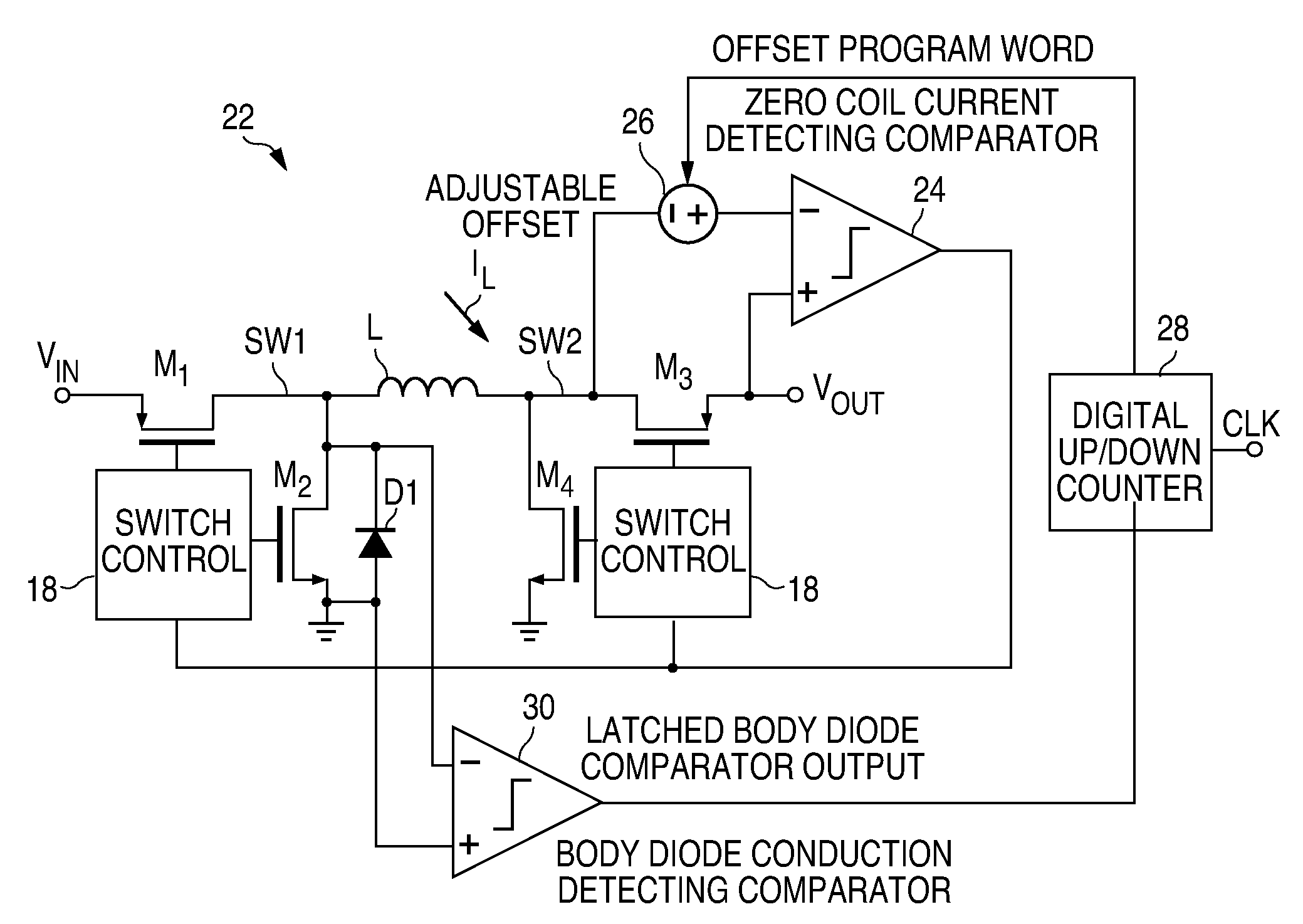
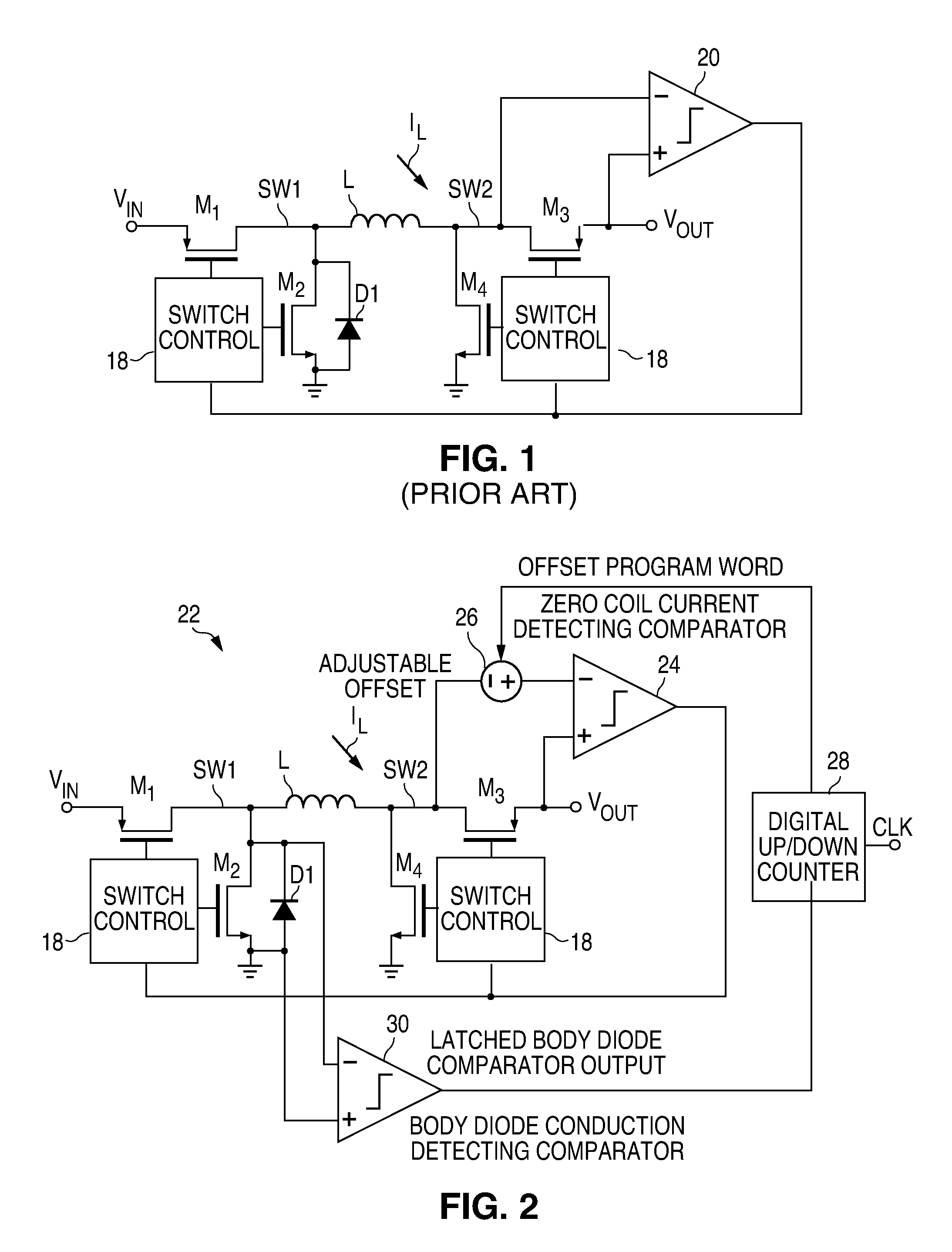
[0021]Referring again to the drawings, FIG. 2 depicts a DC / DC converter, generally designated by the numeral 22, which includes control circuitry in accordance with one embodiment of the present invention. The converter has roughly the same basic architecture at that of FIG. 1 and includes PMOS transistors M1 and M3 and NMOS transistors M2 and M4. An inductor L is connected intermediate switches M1 and M3, with the output filter capacitor not being depicted. Again, switch control circuitry 18 controls the states of switches M1, M2, M3 and M4 as required to provide both buck and boost operation for both PWM and PFM. With a few minor exceptions which will become apparent from the following description, the circuit details of the switch control blocks 18 are conventional and will not be described so as to avoid obscuring the true nature of the present invention in unnecessary detail.
[0022]A zero coil current detecting comparator (ZCCD comparator) 24 is connected across transistor M3 to...
PUM
 Abstract
Description
Claims
Application Information
 - R&D
- Intellectual Property
- Life Sciences
- Materials
- Tech Scout
- Unparalleled Data Quality
- Higher Quality Content
- 60% Fewer Hallucinations
Browse by: Latest US Patents, China's latest patents, Technical Efficacy Thesaurus, Application Domain, Technology Topic, Popular Technical Reports.
© 2025 PatSnap. All rights reserved.Legal|Privacy policy|Modern Slavery Act Transparency Statement|Sitemap|About US| Contact US: help@patsnap.com