Method for avoiding turbocharger damage

a technology of turbocharger and engine, which is applied in the direction of engine starters, electric control, instruments, etc., can solve the problems of rapid shutting down of the internal combustion engine from an operating state, interruption of lubricant supply, and difficulty in coping with the operating state, so as to reduce the fuel consumption and the emission of exhaust gas, and increase the risk

Active Publication Date: 2012-05-17
FORD GLOBAL TECH LLC
View PDF6 Cites 32 Cited by
  • Summary
  • Abstract
  • Description
  • Claims
  • Application Information

AI Technical Summary

Benefits of technology

[0006]Start / stop devices for motor vehicles are known in which the operating state of the vehicle and of the operator control pedals, for example the accelerator pedal and / or brake pedal, are determined and evaluated in order to switch off and start the internal combustion engine again. Such start / stop devices are suitable particularly for vehicles in short-range traffic or town traffic in order to reduce the fuel consumption and the exhaust gas emissions. They are now found in widespread application both in conventional motor vehicles and in low-energy vehicles, hybrid vehicles and the like.
[0007]Combining an internal combustion engine which can be supercharged by a turbocharger with a start / stop automatic system therefore heightens the risk of what is referred to as “hot-soak”, that is to say the destruction or damaging of the turbocharger, that is to say carbonization of the turbocharger, in particular of the lubricating oil which is present in the rotor bearings.

Problems solved by technology

An operating state which is particularly difficult to cope with for this reason is the rapid shutting down of the internal combustion engine from an operating state with a high load.
The supply of lubricant is interrupted when stopping occurs and the conduction of heat away from the shaft is no longer ensured.
This results in overheating of the lubricant oil and an associated carbonization of the lubricating oil remaining in the exposed parts of the bearings, as a result of the subsequent heating of the shaft which is caused by the hot turbine.
The carbonization of the lubricating oil finally causes the rotor bearings to be covered in soot, which is frequently the cause of turbocharger damage.
Combining an internal combustion engine which can be supercharged by a turbocharger with a start / stop automatic system therefore heightens the risk of what is referred to as “hot-soak”, that is to say the destruction or damaging of the turbocharger, that is to say carbonization of the turbocharger, in particular of the lubricating oil which is present in the rotor bearings.

Method used


Image

  • Method for avoiding turbocharger damage
  • Method for avoiding turbocharger damage
  • Method for avoiding turbocharger damage

Examples


Embodiment Construction

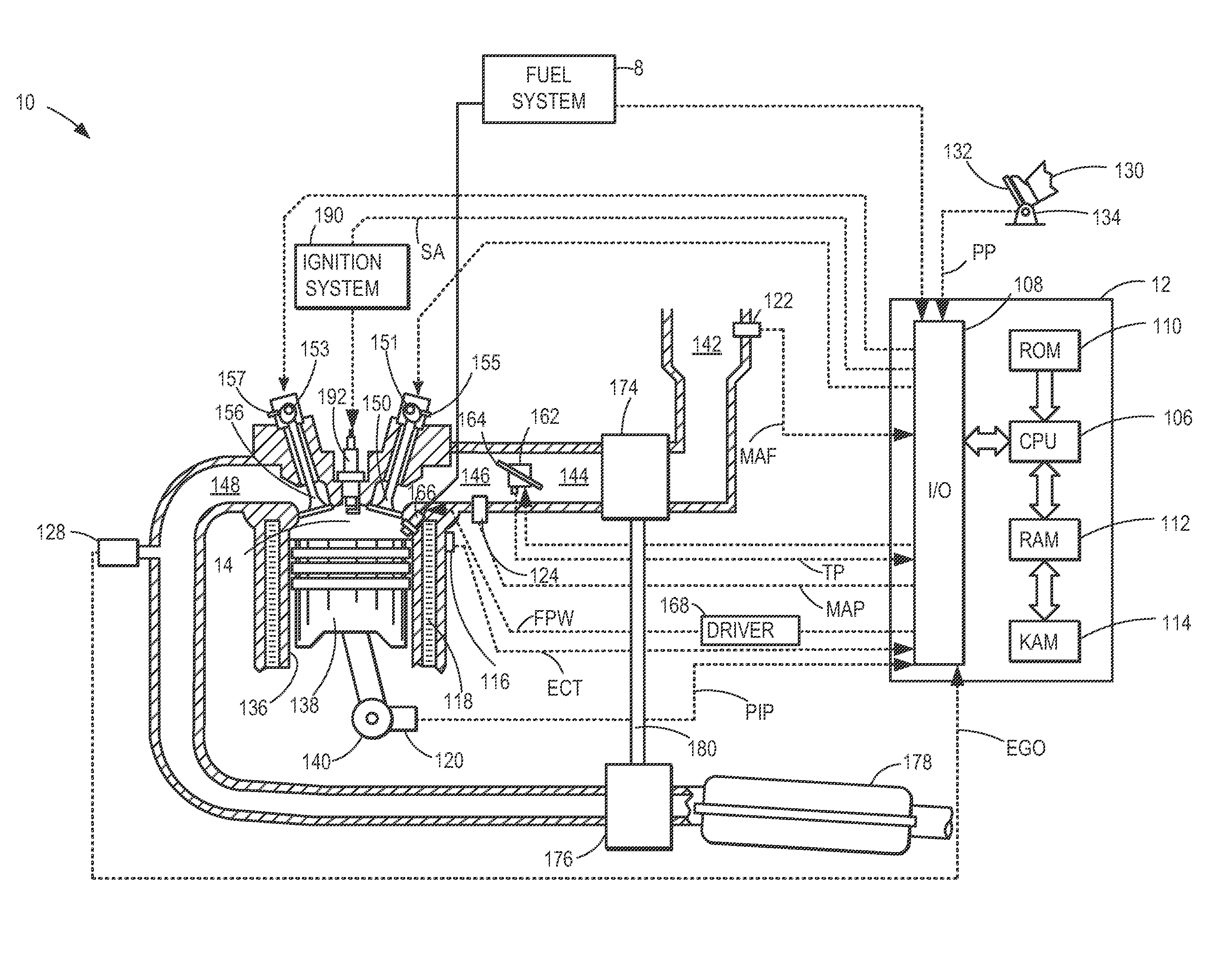
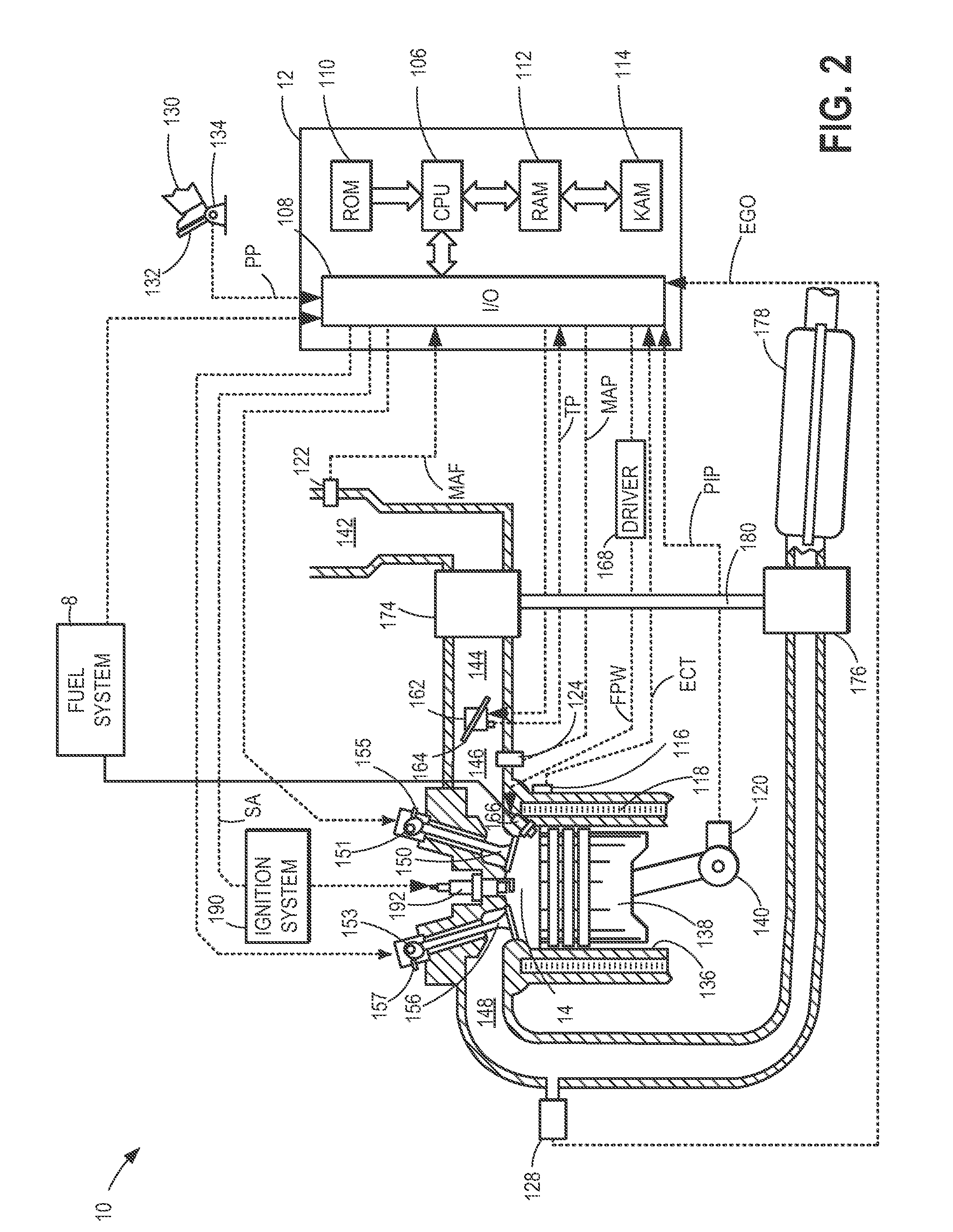
[0019]A turbocharger turbine admits exhaust gas in order to rotate a shaft coupled to a compressor. As a result, the turbine may be exposed to high temperatures. To prevent damage to the turbine, oil may be pumped through the turbine. In vehicles with an automatic start / stop system, the engine may be automatically shut down in response to one or more operating parameters. Under these conditions, an oil pump that pumps oil to the turbine may continue to be operated after engine stop conditions have been met to ensure adequate cooling of the turbine. FIGS. 1-3 show example engine diagrams including an automatic start / stop system, turbocharger, and oil pump. FIG. 4 is a control routine for operating the oil pump. FIG. 5 is example operating parameters during the course of carrying out the control routine of FIG. 4.

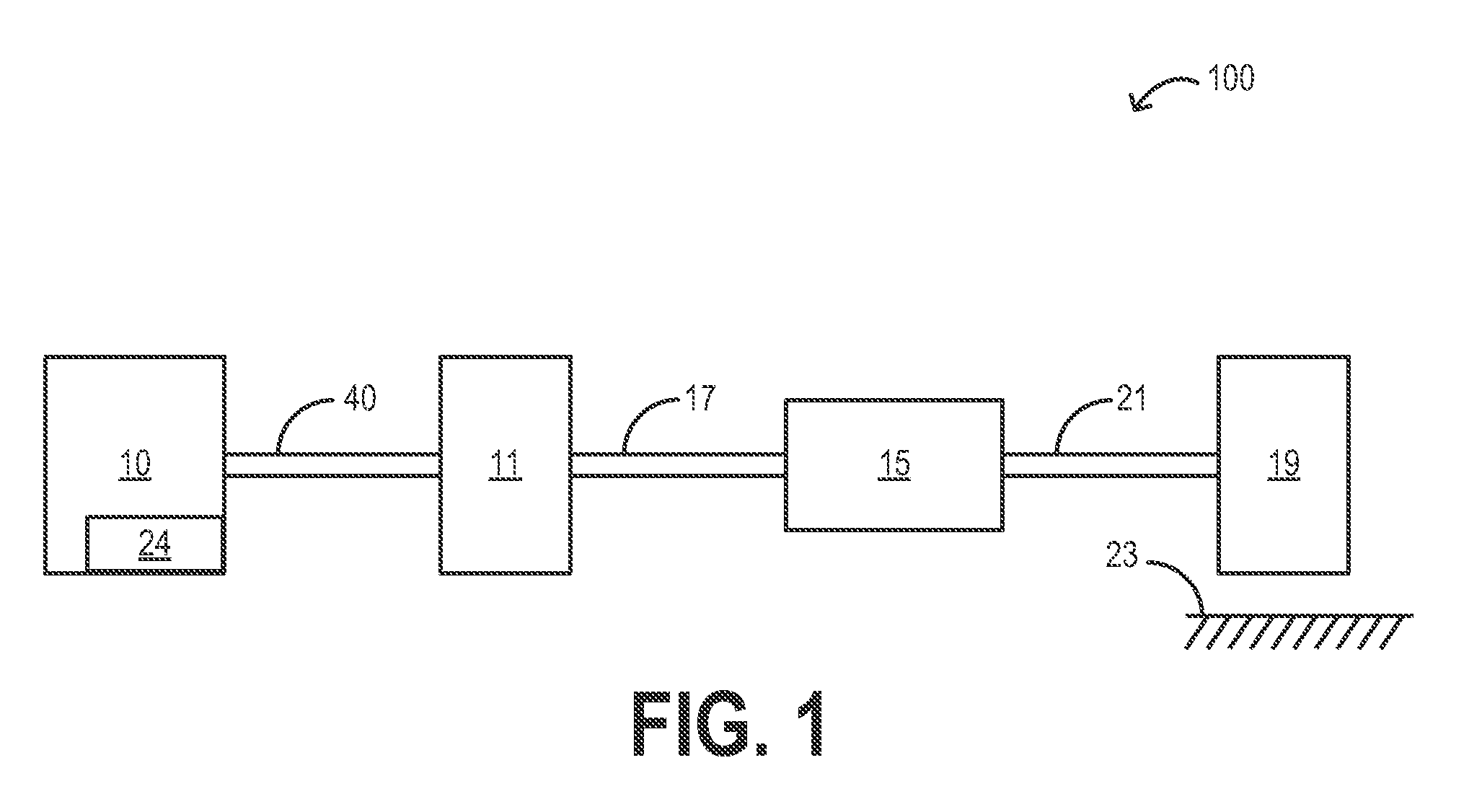
[0020]FIG. 1 shows a vehicle system 100 including internal combustion engine 10 coupled to torque converter 11 via crankshaft 40. Engine 10 may be a gasoline engine. In alter...


PUM


Abstract

A method for operating an engine of a motor vehicle is provided. The method comprises operating at least one turbocharger, operating a start/stop automatic system which automatically switches off the internal combustion engine when a stop condition is met, and automatically starts the internal combustion engine when a starting condition is met, and when the stop condition is met, delaying the automatic switching off of the internal combustion engine by a predefinable delay time (Δt). In one example, automatic shut off of the engine may be delayed in order ensure adequate cooling of the turbocharger.

Description

RELATED APPLICATIONS[0001]The present application claims priority to German Patent Application No. 102010043920.7, filed on Nov. 15, 2010, the entire contents of which are hereby incorporated by reference.FIELD[0002]The present disclosure relates to a method for operating an internal combustion engine.BACKGROUND AND SUMMARY[0003]Turbochargers and exhaust gas turbochargers are used widely in series-produced motor vehicles, in order to increase the power of the respective vehicle engines. According to the design which is customary today, exhaust gas turbochargers have a rotor with a compressor wheel and a turbine wheel and a shaft which is arranged between the compressor wheel and the turbine wheel and is rotatably mounted in corresponding rotor bearings on the turbine side and the compressor side. The rotor bearings can generally be sliding bearings or roller bearings with oil lubrication. The bearings are usually supplied with lubricant by means of lubricant, for example engine oil,...

Claims


Application Information

Patent Timeline
Patent Type & Authority Applications(United States)
IPC IPC(8): F02D28/00
CPCF01M1/02F01M2001/0215F02D23/00F02D41/0007F02D41/042F02N11/0818Y02T10/48F02N2200/023F02N2200/024F02N2300/2011F16N2260/50Y02T10/144F02N2200/022F01P2060/12Y02T10/12Y02T10/40
Inventor STOFFELS, HARALDSTUMP, LUDWIG
Owner FORD GLOBAL TECH LLC
Why Eureka
Try Eureka