Eureka AIR delivers breakthrough ideas for toughest innovation challenges, trusted by R&D personnel around the world.

Fast quantizer apparatus and method

Inactive Publication Date: 2012-05-24
ASAHI KASEI ELECTRONICS CO LTD
View PDF7 Cites 3 Cited by
  • Summary
  • Abstract
  • Description
  • Claims
  • Application Information

AI Technical Summary

Benefits of technology

[0007]Embodiments provide a low-distortion architecture with reduced loop delay to control stability. Double sampling, quantization and dynamic element matching (DEM) are accomplished within non-overlap time. By reducing the time delay, power can be saved for analog integrators.
[0010]Embodiments (as in FIG. 2) include a fast quantizer comparator device (200) for optimizing delay time comprising at least a regeneration latch (210), comprising an equalization switch (245) between a first regeneration latch output (A 255) and a second regeneration latch output (B 260), and a current source (280) at the tail of the regeneration latch (210) wherein the equalization switch (245) turns on during the resetting time. For other embodiments, the current source (280) provides low DC current. In another embodiment, the regeneration latch comprises a comparison switch (250) at the tail of the regeneration latch (210), wherein the comparison switch (250) turns on during the comparison time. Yet another embodiment further comprises at least a preamplifier (205) connected ahead of the regeneration latch; and at least a data latch (215) connected following the regeneration latch. For further embodiments, time delay is reduced and optimized through initial voltages provided by the preamplifier stage to regeneration latch outputs of the regeneration latch stage.

Problems solved by technology

These demands involve conflicting attributes such as size, cost, complexity, power, speed, signal bandwidth, noise and stability.
While increased adder inputs can obtain more effective feedback, instability can also increase.
Instability can result from circuit delays, especially loop delay.
As mentioned, as the number of adder inputs and coefficients are increased, the adder feedback factor β becomes lower, hence high power consumption to get wide bandwidth or good phase margin.

Method used


Image

  • Fast quantizer apparatus and method
  • Fast quantizer apparatus and method
  • Fast quantizer apparatus and method

Examples


Embodiment Construction

[0016]The following detailed description provides example embodiments of the presently claimed invention with references to the accompanying drawings. The description is intended to be illustrative and not limiting the scope of the present invention. Embodiments are described in sufficient detail to enable one of ordinary skill in the art to practice the subject invention. Other embodiments may be practiced with some variations without departing from the spirit or scope of the subject invention.

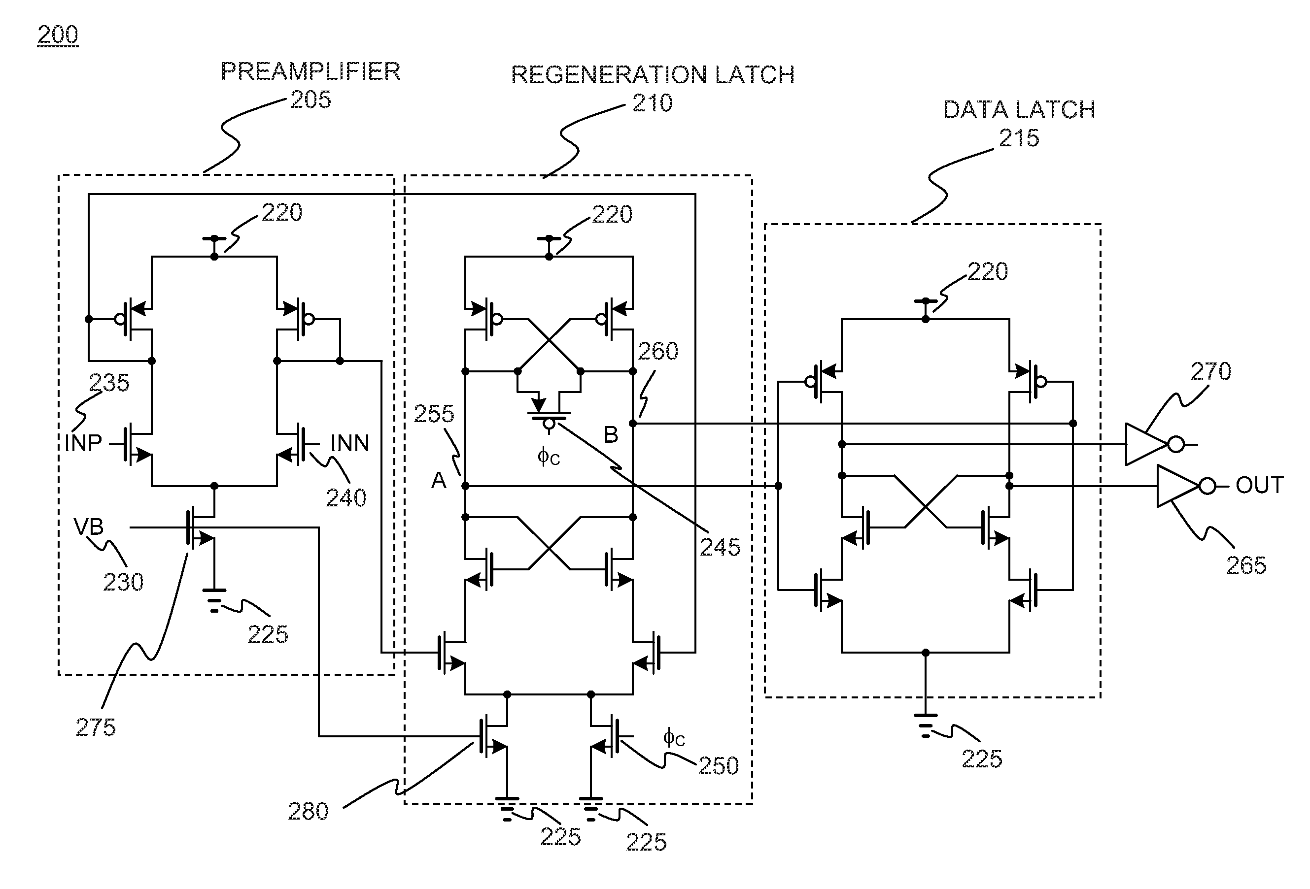
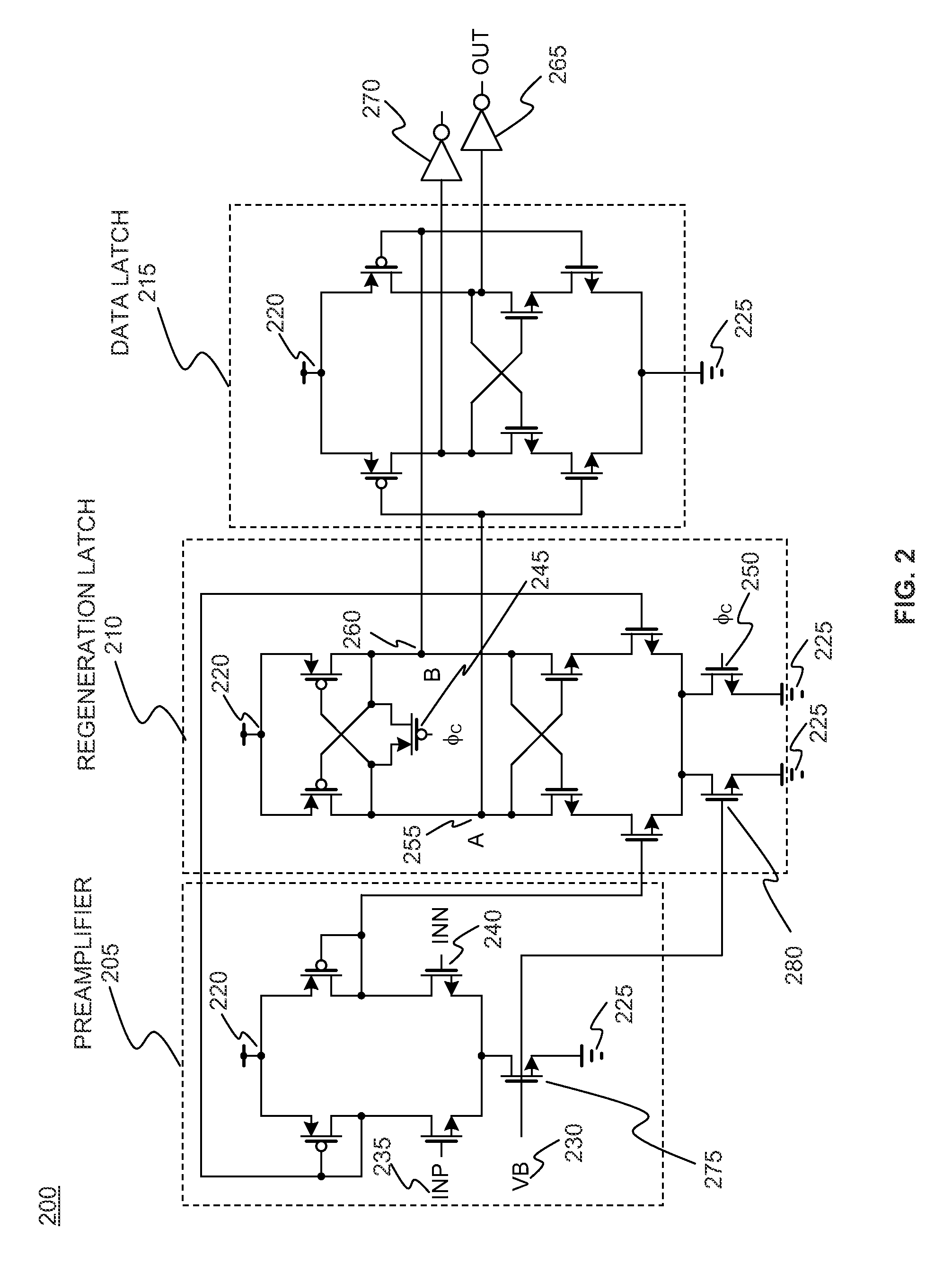
[0017]FIG. 2 depicts a fast quantizer comparator circuit embodiment 200. The circuit comprises three stages: a first preamplifier stage 205, a second regeneration latch stage 210, and a third data latch stage 215. Connections comprise VDD supply connections 220 and ground connections 225. Inputs comprise VB 230, INP 235, and INN 240. Switches comprise φc switches 245 and 250. Outputs comprise regeneration latch output A 255 and regeneration latch output B 260, OUT 265, and 270.

[0018]The secon...


PUM


Abstract

An apparatus and method for a fast quantizer comparator comprising three stages: a preamplifier stage, a regeneration latch stage, and a data latch stage. Time delay is reduced by changing the initial voltages of the regeneration latch outputs. The current source is provided at the tail of the comparator, enabling time delay optimization. When the PMOS equalization switch turns off, it makes the clock signal feedthrough and provides charge injection into the outputs. Because of these charges, the time delay of the comparator is variable. Only a very low current sets the output voltages because the resetting time is longer than the comparison time.

Description

RELATED APPLICATIONS[0001]This application claims the benefit of U.S. Provisional Application No. 61 / 415,041 filed Nov. 18, 2010; this application is herein incorporated in its entirety by reference.FIELD OF THE INVENTION[0002]The invention relates to architectures for low-distortion delta sigma modulators, particularly to a fast quantizer and method providing optimized time delay.BACKGROUND OF THE INVENTION[0003]A wide range of products incorporate high speed circuits that form analog to digital converters (ADCs) and digital to analog converters (DACs). These include delta-sigma (ΔΣ) modulators. Performance expectations of these products are constantly driving designs to achieve greater linearity and bandwidth while limiting or reducing power consumption. The field of signal processing generally is demanding enhanced specifications. These demands involve conflicting attributes such as size, cost, complexity, power, speed, signal bandwidth, noise and stability. Products demanding th...

Claims


Application Information

Patent Timeline
IPC IPC(8): H03M1/06H03M99/00
CPCH03K3/35613H03M3/452H03M3/424
Inventor CHAE, JEONGSEOKTEMES, GABOR C.
Owner ASAHI KASEI ELECTRONICS CO LTD
Why Eureka
Eureka Blog
Learn More