Temperature measuring device

Inactive Publication Date: 2012-05-24
CITIZEN WATCH CO LTD
View PDF0 Cites 25 Cited by
  • Summary
  • Abstract
  • Description
  • Claims
  • Application Information

AI Technical Summary

Benefits of technology

[0020]As described above, according to the present invention, the heat flow path members (heat insulating materials) corresponding to the temperature sensing elements are independently disposed, and the casing having a low thermal conductivity thermally isolates the heat flow path members from each other, which can suppres

Problems solved by technology

Therefore, the heat flow paths in a plane direction exist inside the heat insulating material, which raises a problem that the heat flows affect one another to cause an error in calculation of a

Method used


Image

  • Temperature measuring device
  • Temperature measuring device
  • Temperature measuring device

Examples


first embodiment

Description of Structure of Temperature Measuring Device According to First Embodiment: FIG. 1A, FIG. 1B, and FIG. 2

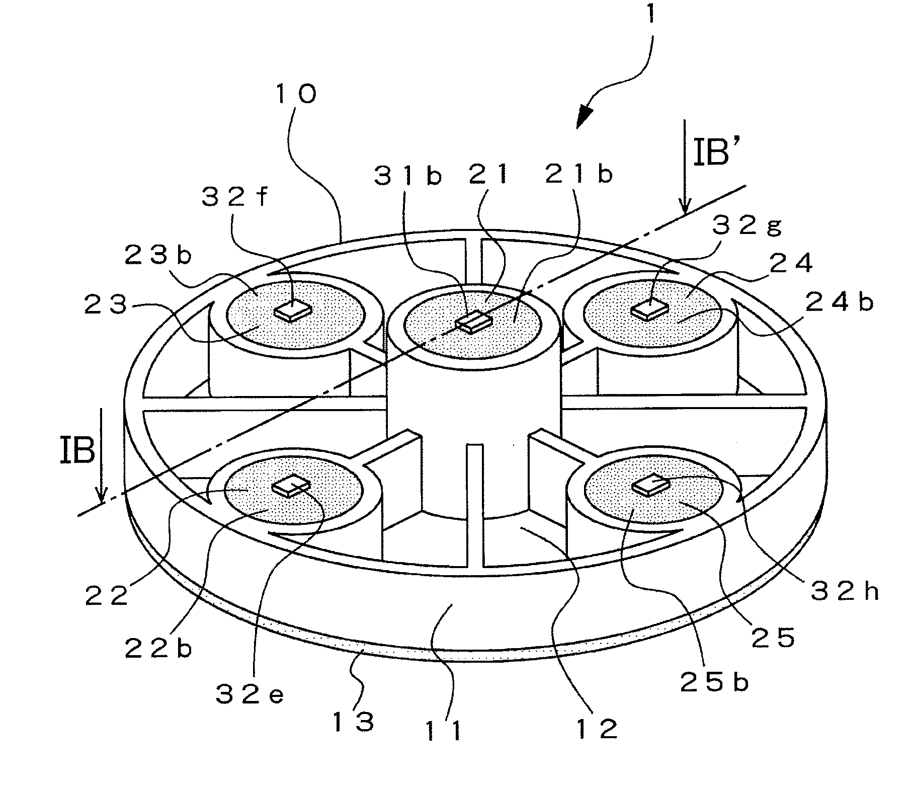
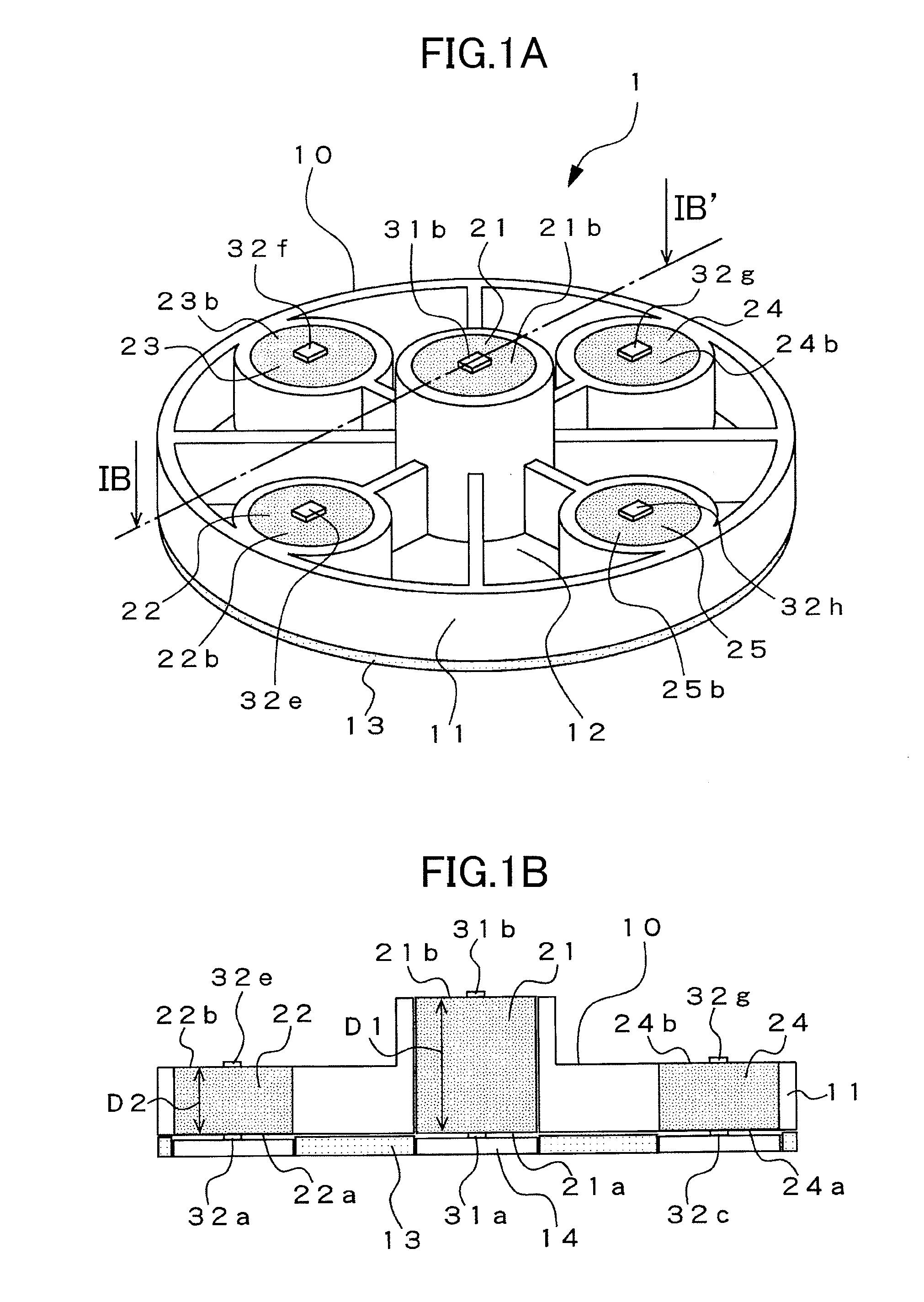
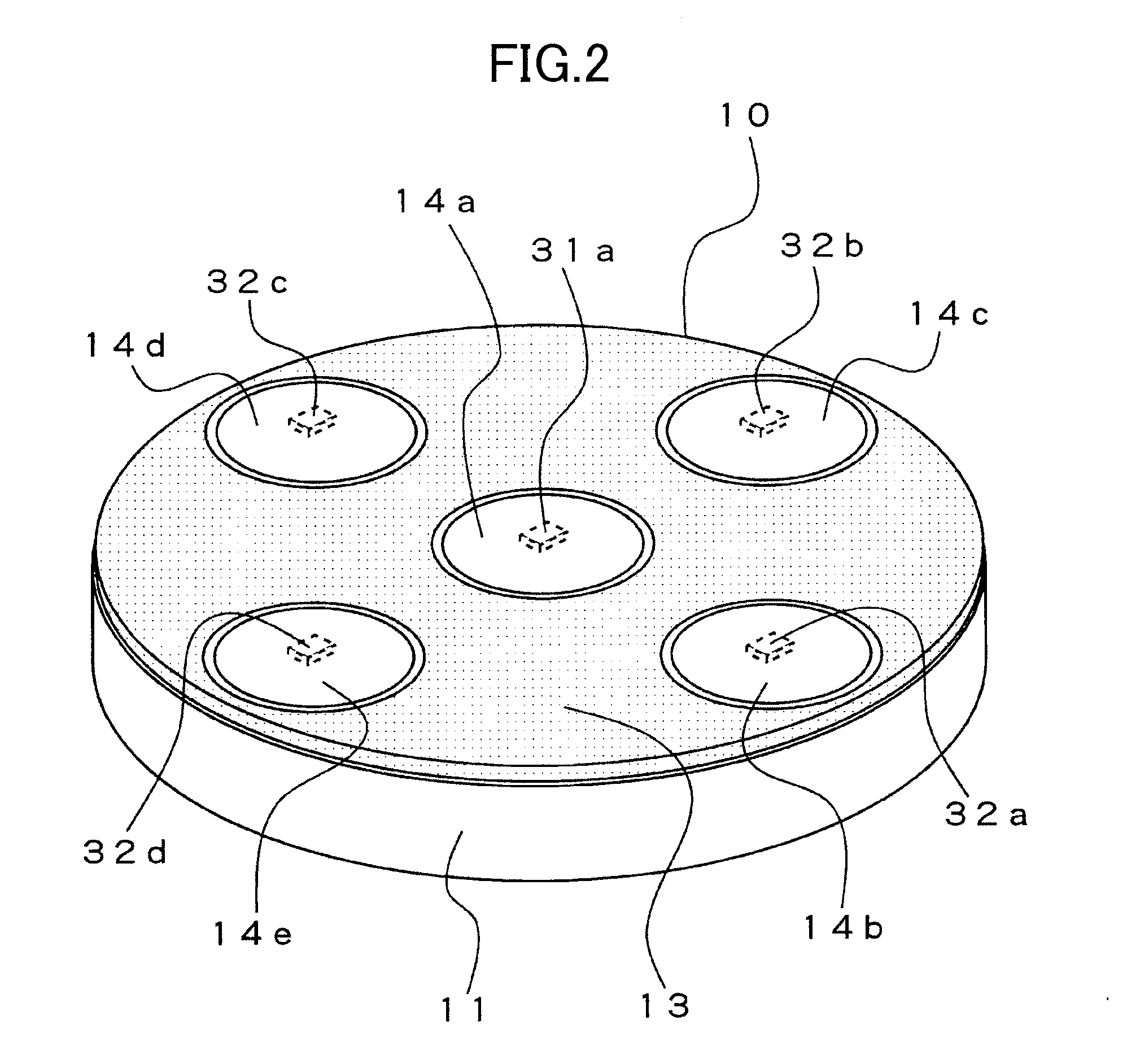
[0037]Referring to FIG. 1A and FIG. 1B, description is made of a structure of a temperature measuring device according to the first embodiment. FIG. 1A is a perspective view of the temperature measuring device according to the first embodiment, and FIG. 1B is a sectional view illustrating a section of a temperature measuring unit of FIG. 1A taken along the cutting plane line IB-IB′ that passes through its center. In FIG. 1A and FIG. 1B, a temperature measuring device 1 according to the first embodiment includes a temperature measuring unit 10 for measuring a temperature of an object to be measured (not shown) in contact therewith and a control unit (see FIG. 3) described later.

[0038]The temperature measuring unit 10 is structured of a casing 11, a first heat flow path member (heat insulating material) 21 located substantially at the center of the casing 11, four second...

second embodiment

[0085]Next, referring to FIG. 8A and FIG. 8B, description is made of a structure of a temperature measuring device according to the second embodiment. FIG. 8A is a perspective view of the temperature measuring unit of the temperature measuring device according to the second embodiment when viewed obliquely from above, and FIG. 8B is a perspective view thereof when viewed obliquely from below (from a back surface thereof). Note that, the second embodiment has the same basic structure as the first embodiment, and hence the same components are denoted by the same reference symbols to partially omit duplicate description.

[0086]As illustrated in FIG. 8A and FIG. 8B, in the temperature measuring unit 10 of the temperature measuring device according to the second embodiment, the casing for isolating the heat flow path members from one another is made of a polystyrene foam 50 having a high thermal resistor. Here, the cylindrical first heat flow path member 21 having a large thickness which ...

third embodiment

[0093]Next, referring to FIG. 9A and FIG. 9B, description is made of a structure of a temperature measuring device according to the third embodiment. FIG. 9A is a perspective view of the temperature measuring unit of the temperature measuring device according to the third embodiment when viewed obliquely from above, and FIG. 9B is a sectional view illustrating a section of the temperature measuring unit of FIG. 9A cut out by the cutting plane line IXB-IXB′ that passes through its center. Note that, the third embodiment has the same basic structure as the first embodiment, and hence the same components are denoted by the same reference symbols to partially omit duplicate description.

[0094]In FIG. 9A and FIG. 9B, the temperature measuring unit 10 is structured of a casing 60, the first heat flow path member 21 located substantially at the center of the casing 60, a second heat flow path member 26, which is disposed so as to surround the periphery of the first heat flow path member 21,...


PUM


Abstract

In order to improve precision in measuring a deep body temperature by suppressing a heat flux in a plane direction while achieving satisfactory contact between a temperature sensing element and a skin, there is provided a temperature measuring device (1) including: temperature sensing elements (31a, 31b, and 32a to 32h) provided to at least one of inlets (21a to 25a) and outlets (21b to 21b) of first and second heat flow path members (21 to 25), respectively; and a casing (11) having a lower thermal conductivity than thermal conductivities of the first and second heat flow path members (21 to 25), for supporting the first and second heat flow path members (21 to 25), in which a gaseous layer or a vacuum layer (12) is formed among the first and second heat flow path members (21 to 25).

Description

CROSS-REFERENCE TO RELATED APPLICATION[0001]The present application claims priority from Japanese application JP 2010-261265 filed on Nov. 24, 2011, the content of which is hereby incorporated by reference into this application.BACKGROUND OF THE INVENTION[0002]1. Field of the Invention[0003]The present invention relates to a temperature measuring device including a heat flow path member and a temperature sensing element, for estimating a deep body temperature from temperature information on a body surface, in particular, a temperature measuring device for measuring a deep body temperature with high precision by suppressing a heat flux from a heat flow path member in a plane direction, that is, a leakage of a heat flow from the heat flow path member.[0004]2. Description of the Related Art[0005]Up to now, for example, JP 2007-315917 A discloses, in page 6 and FIG. 5C, a deep temperature measuring device including a deep temperature probe and a communication display device. Hereinafter...

Claims


Application Information

Patent Timeline
IPC IPC(8): G01K17/00
CPCG01K13/002G01K7/42G01K13/20G01K7/427
Inventor TSUCHIDA, MASATOMURAMATSU, MASAHIRO
Owner CITIZEN WATCH CO LTD
Why Eureka
Try Eureka