
Binaural noise reduction

a binaural noise and reduction technology, applied in the field of binaural noise reduction, can solve the problems of difficult prediction of the perceptual effects of introducing these artificial streaming cues, more controversy over the effects of spectral and temporal noise reduction on intelligibility and sound quality, and disrupt the internal binaural processes of most listeners, so as to save power

Active Publication Date: 2012-05-24
SONOVA AG
View PDF12 Cites 31 Cited by
  • Summary
  • Abstract
  • Description
  • Claims
  • Application Information

AI Technical Summary

Benefits of technology

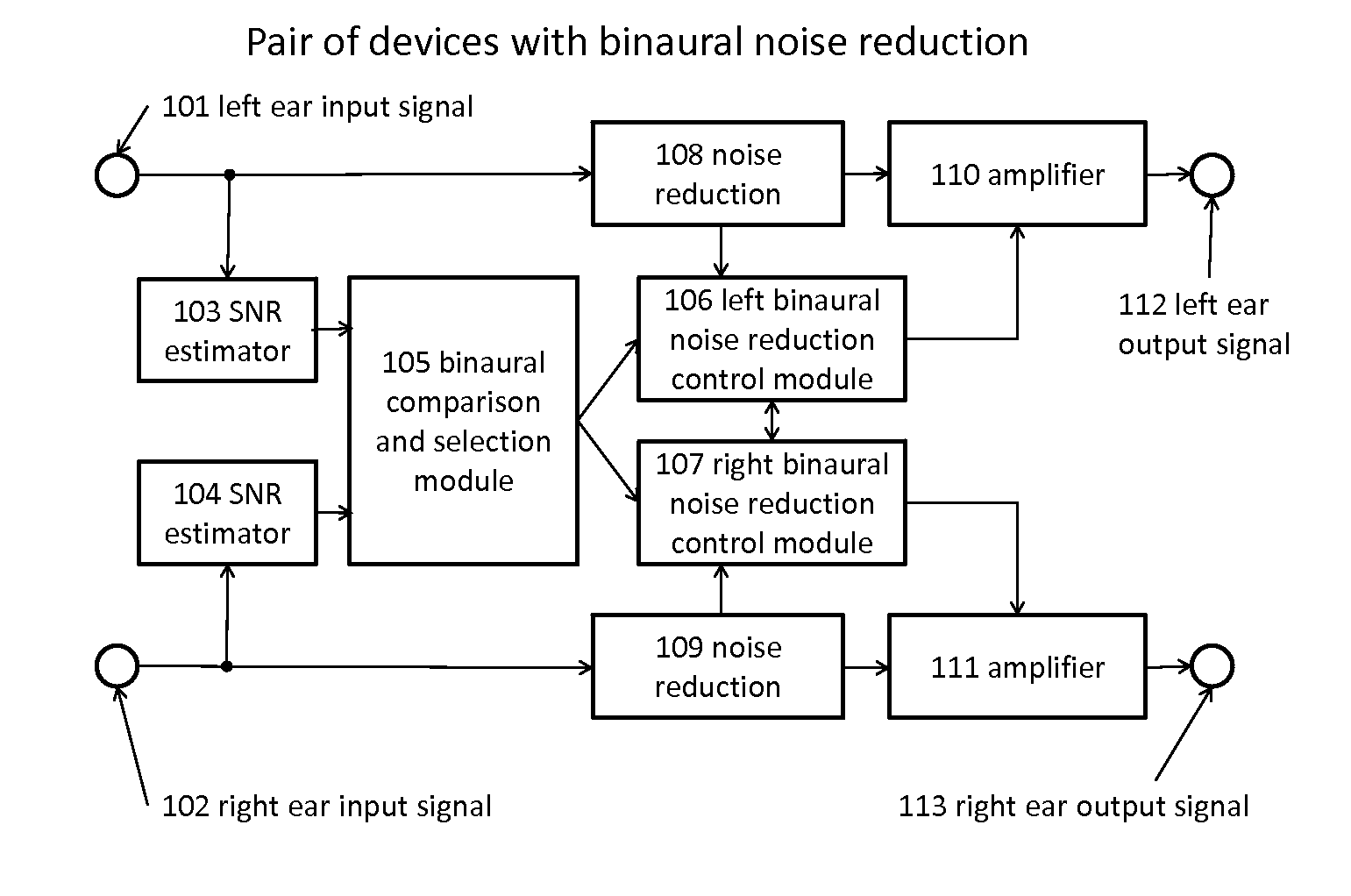
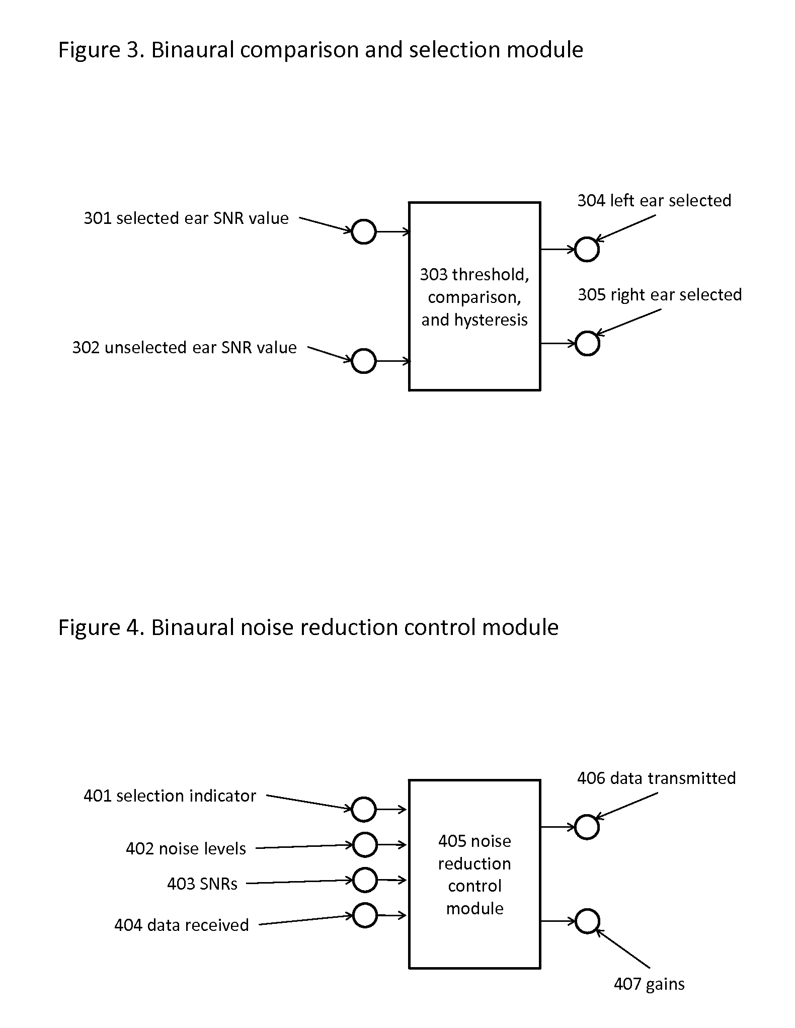
[0033]In one embodiment of the invention, the noise reduction scheme is a multichannel expansion scheme or spectral subtraction scheme which temporarily reduces the gain applied to frequency bands that are thought to be primarily noise, and increases the gain in frequency bands that are thought to be primarily signal. The choice between whether a frequency band contains primarily noise or signal is preferably based on instantaneous amplitude and dynamic range of the sound in that frequency band in the selected ear. The reduction or increase in gain is applied equally and simultaneously to the signal for both ears. The control signals derived from the selected ear signal can be particularly simple in this case, for example, a 32-channel noise reduction scheme can be controlled by sending 32 bits to encode whether each channel is primarily signal (bit value=1) or noise (bit value=0).
[0036]The changes to the gains in individual frequency channels of the noise reduction processing or in the individual frequency channels of the amplifiers are preferably made slowly enough and over a time scale that is long enough to avoid the generation of artificial sound events and streaming cues. Any faster changes that may be necessary to avoid discomfort or damage to hearing are preferably applied across a broad frequency range and are also applied identically and simultaneously to each ear.
[0039]The wired or wireless communication link between the two devices is preferably disabled when the signal-to-noise-ratio in each ear is greater than a configurable threshold value, and enabled when the signal-to-noise-ratio is below the configurable threshold. The purpose of this refinement is to save power when binaural noise reduction is not required or would not provide any discernable improvement to sound quality or speech intelligibility.

Problems solved by technology

It is also clear that spectral and temporal noise reduction improves comfort, but the effects of spectral and temporal noise reduction on intelligibility and sound quality are more controversial.
If these cues are changed differently in the left and right ears, they may also disrupt the internal binaural processes that most listeners rely upon most heavily in noisy situations.
The perceptual effects of introducing these artificial streaming cues are difficult to predict.
On the other hand they will make it more difficult for the internal auditory streaming processes to separate the desired sound events and streams from the noise events and streams.
If the artificial streaming cues created by the external noise reduction are different in the two ears, they will add further to the confusion between what is the desired sound stream and what is the noise stream.

Method used


Image

  • Binaural noise reduction
  • Binaural noise reduction
  • Binaural noise reduction

Examples


second embodiment

[0050]In the invention, the gains or gain reductions for each frequency channel are calculated in the selected ear in the same manner as for a conventional monaural noise reduction scheme and transmitted from the selected ear to the unselected ear and applied simultaneously to the signal for each ear.

third embodiment

[0051]In the invention, the amplitude and dynamic range (or signal-to-noise ratio) for each frequency band are transmitted from the selected ear to the unselected ear and applied in identical noise reduction algorithms in both ears simultaneously.

[0052]The advantages of these embodiments of the present invention comprise: more accurate assessment of signal and noise levels in the unselected ear by utilizing information from the ear with the better SNR; avoidance of the creation of artificial streaming events that could disrupt the normal binaural processing of sounds; emphasize the signal relative to the noise in such a manner as to improve the signal-to-noise ratio in the unselected ear; minimizing the data transmission requirements and hence minimizing the additional power consumption of the devices; intelligently switching data transmission from one ear to the other to halve power consumption relative to a device that always transmits data in both directions; and intelligently sw...


PUM


Abstract

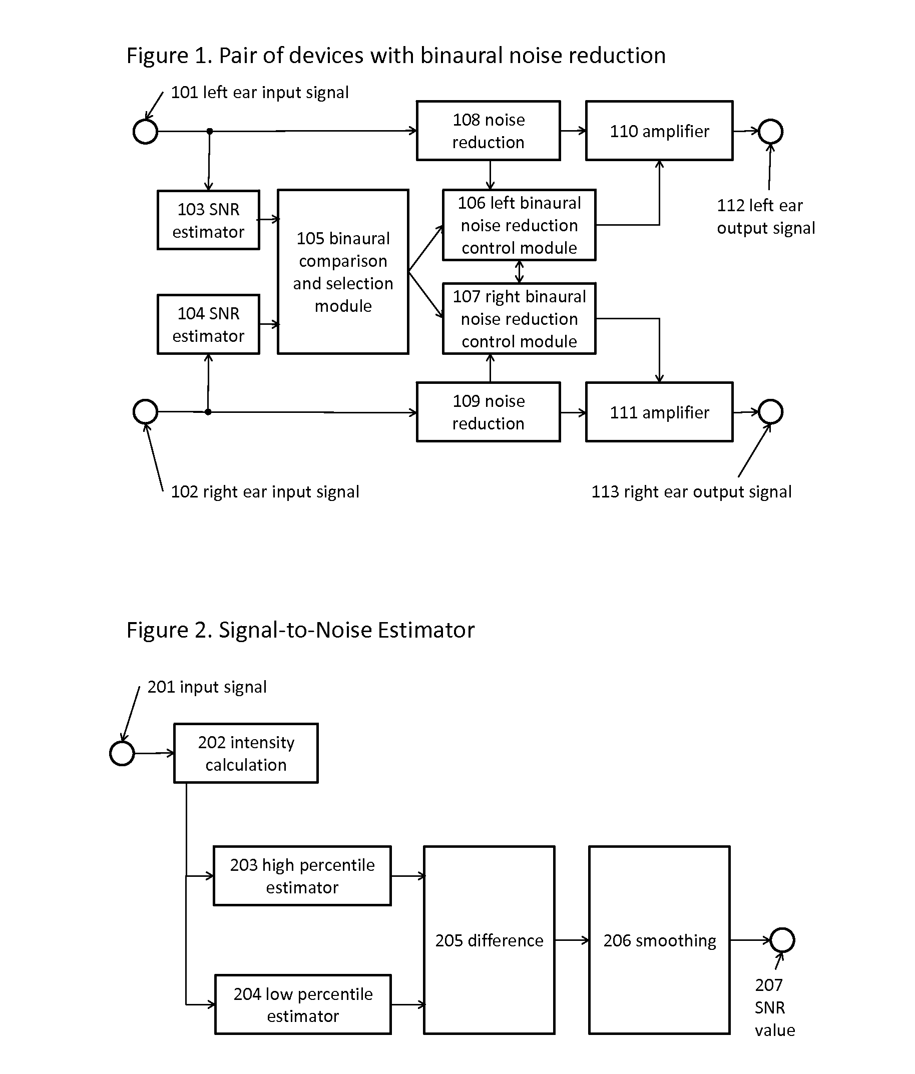
In one embodiment, the present invention provides a sound processing device with a binaural input and binaural output, where “binaural input” means at least one microphone mounted in or near each ear of the device user, and “binaural output” means at least one output signal directed to each ear. The device may be comprised of two parts connected by a wired or wireless link. The device comprises: at least one microphone in or near each ear for the transduction of the sound at each ear; a signal-to-noise estimation module to estimate the signal-to-noise ratio present at each ear; a comparison and selection module to compare the signal-to-noise ratios present at the two ears and select the ear with the greater signal-to-noise ratio; a noise reduction control module that uses the spectral and temporal information from the selected ear signal to control two identical noise reduc tion modules; two identical noise reduction modules that process the signals from the two ears, under the control of the control module; and two output modules that amplify the output signals from the noise reduction modules appropriately for each ear and present the amplified signals as sound or other signals to each ear of the device user. The device may be implemented in dedicated hardware embodiment or by software running on a microprocessor.

Description

FIELD OF THE INVENTION[0001]The present invention relates to sound processing devices in which an acoustic sound input or an electric or digital representation of an acoustic sound input is processed and converted to an acoustic or electric sound output, and in particular relates to the processing of sound in noisy environments to improve speech intelligibility, sound quality, and naturalness of the sound. Sound processing devices of this kind are often used in hearing aids, assistive listening devices (ALD), and consumer audio devices such as radios, television sets, CD players, MP3 players, stereo systems, headsets, telephones, and mobile phone handsets. The Global Medical Device Nomenclature Agency (GMDNS) definition of an ALD is an amplifying device, other than a hearing aid, for use by a hard of hearing person. In the case of an electric sound output, sound processing devices of this kind are used in cochlear implants.BACKGROUND OF THE INVENTION[0002]Sound processing devices, i...

Claims


Application Information

Patent Timeline
Patent Type & Authority Applications(United States)
IPC IPC(8): H04R5/00
CPCH04R5/04H04S1/002H04R25/552H04R25/407
Inventor BLAMEY, PETER
Owner SONOVA AG
Learn More