
Method and Apparatus for Controlling the Drive System for Mobile Equipment such as a Mobile Construction and/or Mining Machine

a technology of drive system and mobile equipment, which is applied in the direction of process and machine control, electric devices, instruments, etc., can solve the problems of increased frame fatigue, torque difference, and of course unfavorable vehicle torque difference, so as to avoid chassis fatigue and minimize stress and oscillations

Active Publication Date: 2012-05-24
LIEBHERR MINING EQUIP
View PDF19 Cites 6 Cited by
  • Summary
  • Abstract
  • Description
  • Claims
  • Application Information

AI Technical Summary

Benefits of technology

[0017]Therefore, it is an objective of the present invention to provide an improved method and apparatus for controlling the drive system for a mobile construction and / or mining machine of the aforementioned type which avoid the disadvantages of the prior art and provide further developments thereof. More particularly, the drive system should be configured to minimize stresses and oscillations in the frame and suspension members of the machine due to differences in wheel speeds and to avoid fatigue in the chassis and suspension structures.
[0019]More particularly, the present invention allows for differences in the power supply to the separate electric traction motors and does no longer maintain equal power to all electric traction motors despite the fact that the operator may choose a desired vehicle speed and / or command a desired drive power output such as “maximum output” or “75% output”. To achieve a reduction of oscillating stresses in the frame and suspension elements, the control strategy provides for uniform torque between the electric traction motors. Taking into account the characteristic torque / speed curve of an electric traction motor operated in the constant power range, the traction motor power output is varied when the motor speed varies to compensate for unbalanced torque output. In accordance with the present invention, when the operator's drive commander is kept constant, the electric traction motors are controlled by a torque controller to provide uniform torque, wherein deviations in speeds of the electric traction motors are determined and electric motor power of at least one of said electric traction motors is varied relatively to the electric motor power of the other electric traction motor in response to a determined deviation in speed to keep the torques of the electric traction motors uniform. The power control balancing compensates for the torque differences previously encountered when the speeds of the traction motors differ at equal power supplied to the traction motors.
[0020]According to a preferred embodiment of the invention, the power control balancing may be adopted such that the total power output of all traction motors is kept constant. More particularly, upon detection of a deviation in speeds of the electric traction motors, the electric motor power of a traction motor running at a faster speed is increased whereas the motor power of the other traction motor running at a slower speed is decreased such that not only the torques are kept uniform, but the sum of the motor powers of the plurality of traction motors is kept constant. The increase in power output of one traction motor is balanced or compensated by the reduction in power output of the other traction motor(s). According to a preferred embodiment, as long as the motor capacity and / or power supply capacity allows, the torque of all traction motors can be kept at the level that would be provided by each motor when there would be no speed difference and equal power were supplied to each motor to meet the operator's command. To achieve such maintenance of the desired power output, the motor power of the motor running at increased speed is increased such that the torque decrease due to speed increase is compensated, whereas the motor power of the traction motor running at decreased speed is decreased to compensate for the torque increase. As the time of the deviations in speeds is usually brief, thermal concerns of overloading the motor the power of which is increased, do not apply. On the other hand, as the summation of the left and right traction motor powers is kept constant—although the left and right motor powers are allowed to differ from each other -, overload of the power supply, i..e in particular the combustion engine driving the electric generator, is prevented.
[0021]On the other hand, if a drive system is not capable of intermittently going beyond the rated power, then a control is utilized to respect motor power limits at the expense of total power to the ground. More particularly, upon detection of a deviation in speeds of the electric traction motors, the electric motor power of the traction motor with the faster speed may be increased up to or may be kept at a rated maximum power to keep the torque of said traction motor as close as possible to the torque provided by the motor at the desired machine speed and / or desired power output according to the operator's command, whereas the electric power of the other electric traction motor is reduced such that the torques of the traction motors are kept uniform. Such control scheme provides for a reduction in total power output, however, torque differences between the traction motors are avoided and thus undesired stresses and oscillations of the frame and suspension members are prevented.

Problems solved by technology

In both cases, the resulting deviations of the traction motor speeds of the left and right drives cause torque differences when applying common drive control strategies.
Such torque difference is of course unfavourable for the vehicle.
It can result incounter-steering torque, that means the torque difference opposes the turning direction,uneven frame loading leading to an increased frame fatigue.
Similarly, the aforementioned individual motor speed fluctuations resulting from uneven ground, suspension and tyre dynamics may cause deviations in motor speeds.
Such torque differences due to speed differences of the electric traction motors may cause stresses and oscillations in the frame and suspension elements, thereby reducing strength and in worst case creating microcracks in the structures.

Method used


Image

  • Method and Apparatus for Controlling the Drive System for Mobile Equipment such as a Mobile Construction and/or Mining Machine
  • Method and Apparatus for Controlling the Drive System for Mobile Equipment such as a Mobile Construction and/or Mining Machine
  • Method and Apparatus for Controlling the Drive System for Mobile Equipment such as a Mobile Construction and/or Mining Machine

Examples


Embodiment Construction

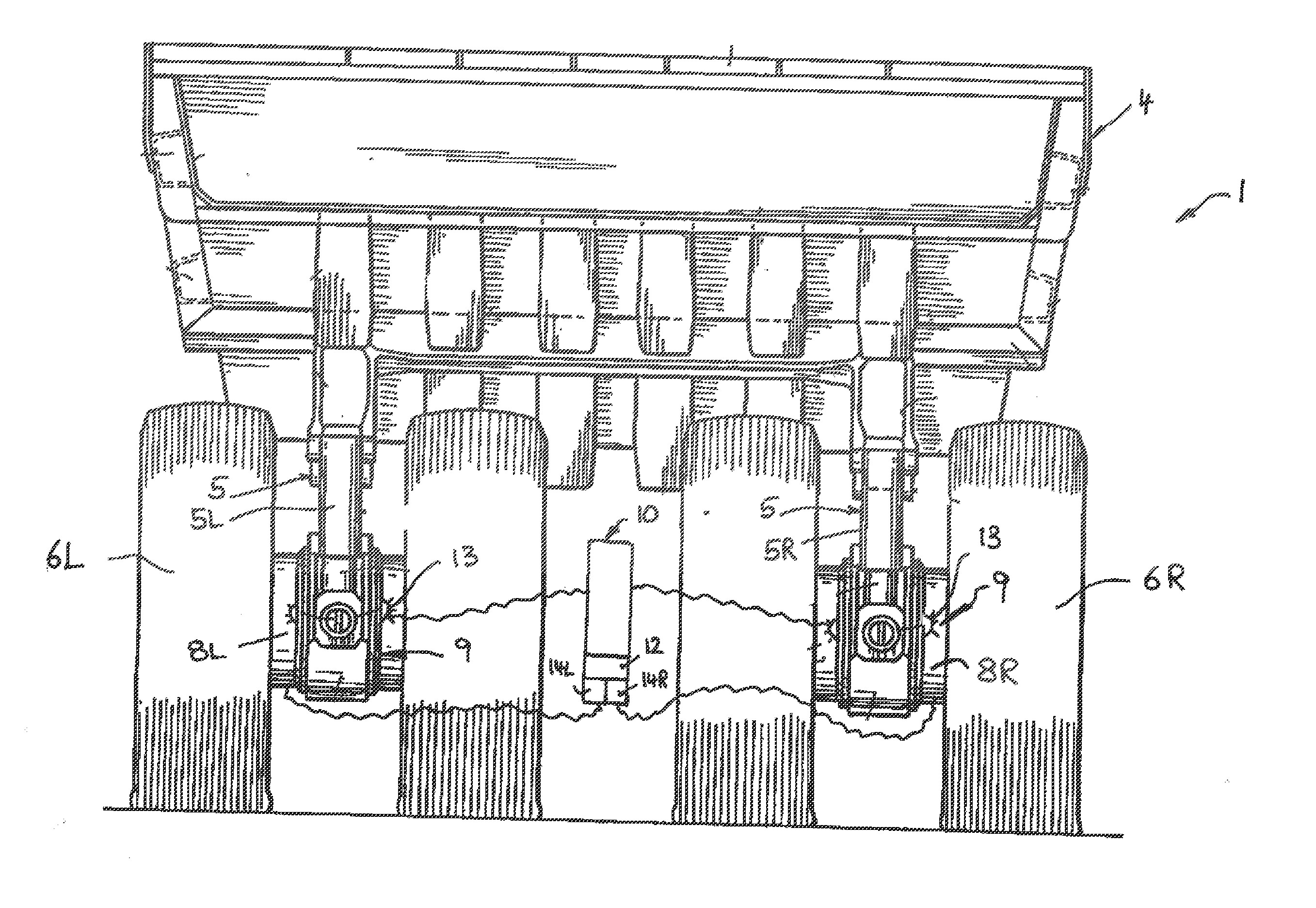
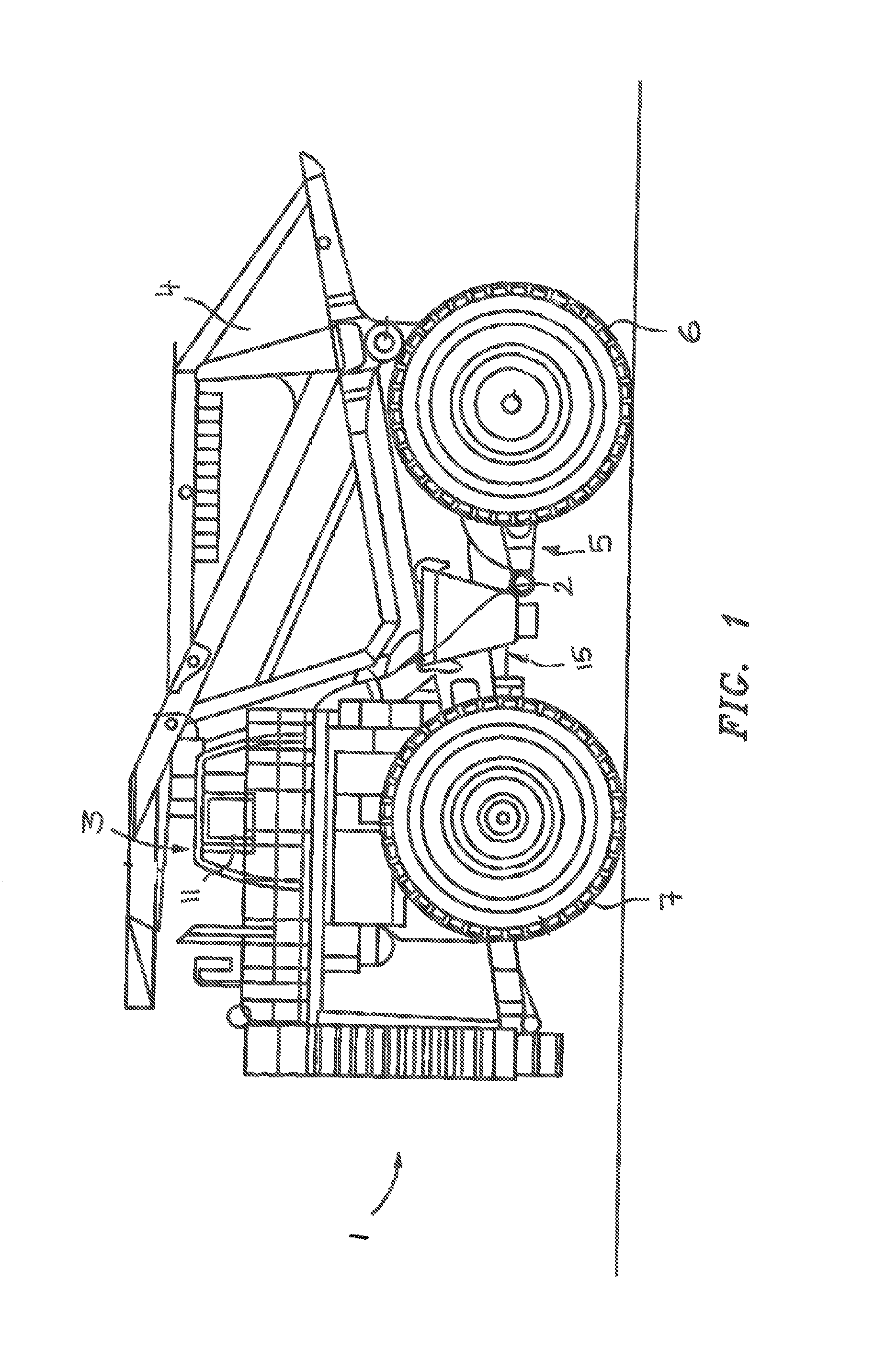
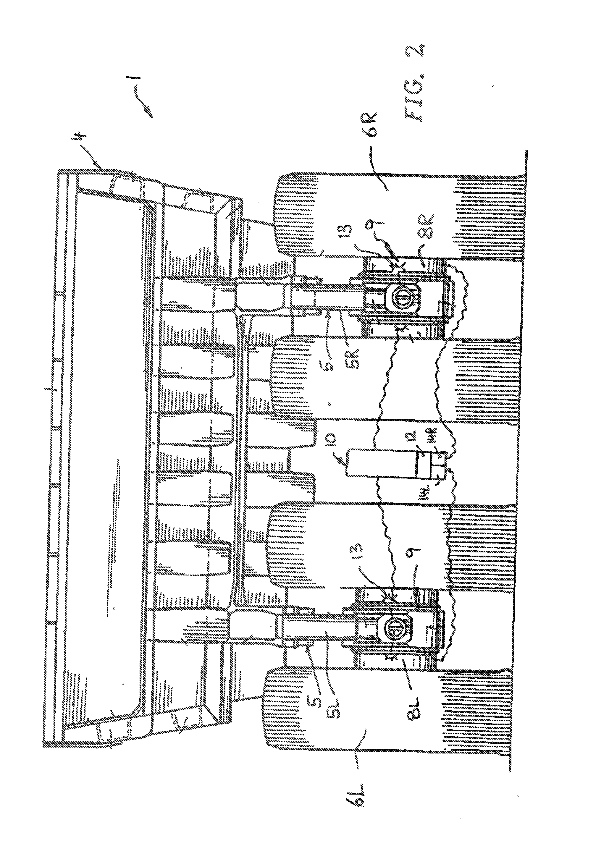
[0031]The large dump truck or mining truck 1 shown in the drawing includes a dump body or dump container 4 which is supported on a frame 2 which is supported on the ground via a chassis 15. An operator's cabin 3 is seated on the frame 2 in a manner known per se and extends above the front wheels 7 of the chassis 4. At least two rear wheels 6, e.g. two pairs of rear wheels 6L and 6R are provided at the rear axle of the chassis 15 which are advantageously driven separately by individual wheel drives. As can be seen from FIG. 2, a suspension 5 may include a left suspension assembly 5L for suspending a pair of left rear wheels 6L and a right suspension assembly 5R for suspending a pair of right rear wheels 6R. However, other embodiments of the suspension 5 are possible.

[0032]In the shown embodiment, the drive system 9 for driving the said rear wheels 6 includes separate traction motors 8R and 8L for driving the right and left rear wheels 6R and 6L individually, wherein it is possible to...


PUM


Abstract

The present invention relates to a method and an apparatus for controlling the drive system for mobile equipment, when the operator's drive commander is kept constant, electric traction motors are controlled by a torque controller to provide uniform torque, deviations in speeds of the electric traction motors are determined and electric motor power of at least one is varied relatively to the electric motor power of the other in response to a determined deviation in speed to keep the torques uniform. The power control balancing compensates for the torque differences previously encountered when the speeds of the traction motors differ at equal power supplied to the traction motors.

Description

BACKGROUND OF THE INVENTION[0001]The present invention relates to a method and an apparatus for controlling the drive system for mobile equipment such as a mobile construction and / or mining machine, in particular mining truck, said drive system comprising at least two electric traction motors for driving separate wheels or separate crawler chains of said mobile construction and / or mining machine and a control unit for controlling speed, power output and / or torque of said electric traction motors, said control unit comprising an operator's drive commander for choosing a desired machine speed and / or desired power output.[0002]Mobile construction and / or mining machines such as mining trucks or crawler chain vehicles often have an electric drive system including separate electric traction motors for individually driving some or all of the wheels wherein, when equipped with a crawler chain, said wheels may include driving wheels for driving the crawler chains. Usually a left traction mot...

Claims


Application Information

Patent Timeline
IPC IPC(8): B60L15/20B60P1/28B60K1/02B60L50/10
CPCB60L11/02B60L15/2036B60L2200/36B60L2220/46B60L2240/421Y02T10/70Y02T10/646Y02T10/7077Y02T10/648Y02T10/7275B60L2240/423B60L50/10Y02T10/64Y02T10/7072Y02T10/72
Inventor WHITFIELD, JAMES A.
Owner LIEBHERR MINING EQUIP
Learn More