Adhesive joining for powder metal components

a technology of powder metal components and adhesives, which is applied in the direction of rod connections, couplings, machines/engines, etc., can solve the problems of difficult fabrication, difficult fabrication, and inability to easily ground the flat surfa

Active Publication Date: 2012-05-31
SKN SINTER METALS LLC (US) +1
View PDF7 Cites 41 Cited by
  • Summary
  • Abstract
  • Description
  • Claims
  • Application Information

AI Technical Summary

Benefits of technology

[0009]The present invention uses adhesive to join multiple powder metal components together. By fabricating the powder metal components separately and then adhesively joining them together to form an assembly, there is an opportunity before joining the components to machine some of the surfaces that would be difficult to machine if the part was formed as a unitary body instead of as a...

Problems solved by technology

However, some complex parts have dimensional requirements that make their fabrication difficult, even using powder metallurgy.
For example, a variable valve timing (VVT) rotor has many features and dimensional requirements that make fabrication difficult.
During part fabrication, this flat surface can not be easily ground because of the adjacent surface.
However, these techniques are very expensive, require skilled labor, and take time to perf...

Method used


Image

  • Adhesive joining for powder metal components
  • Adhesive joining for powder metal components
  • Adhesive joining for powder metal components

Examples


Embodiment Construction

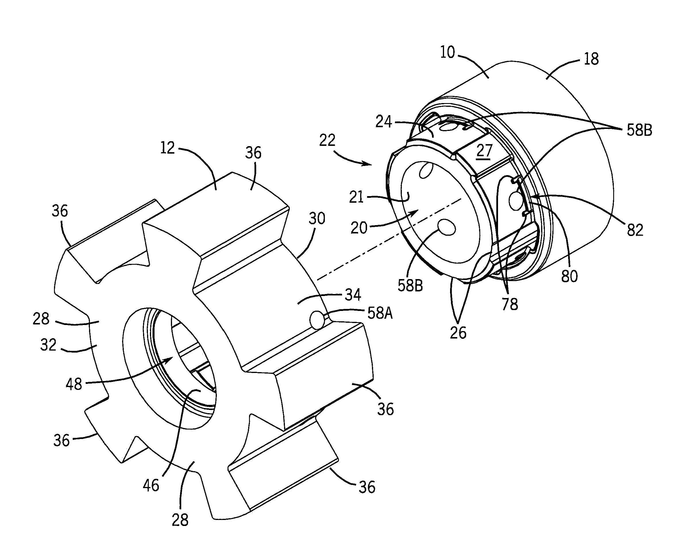
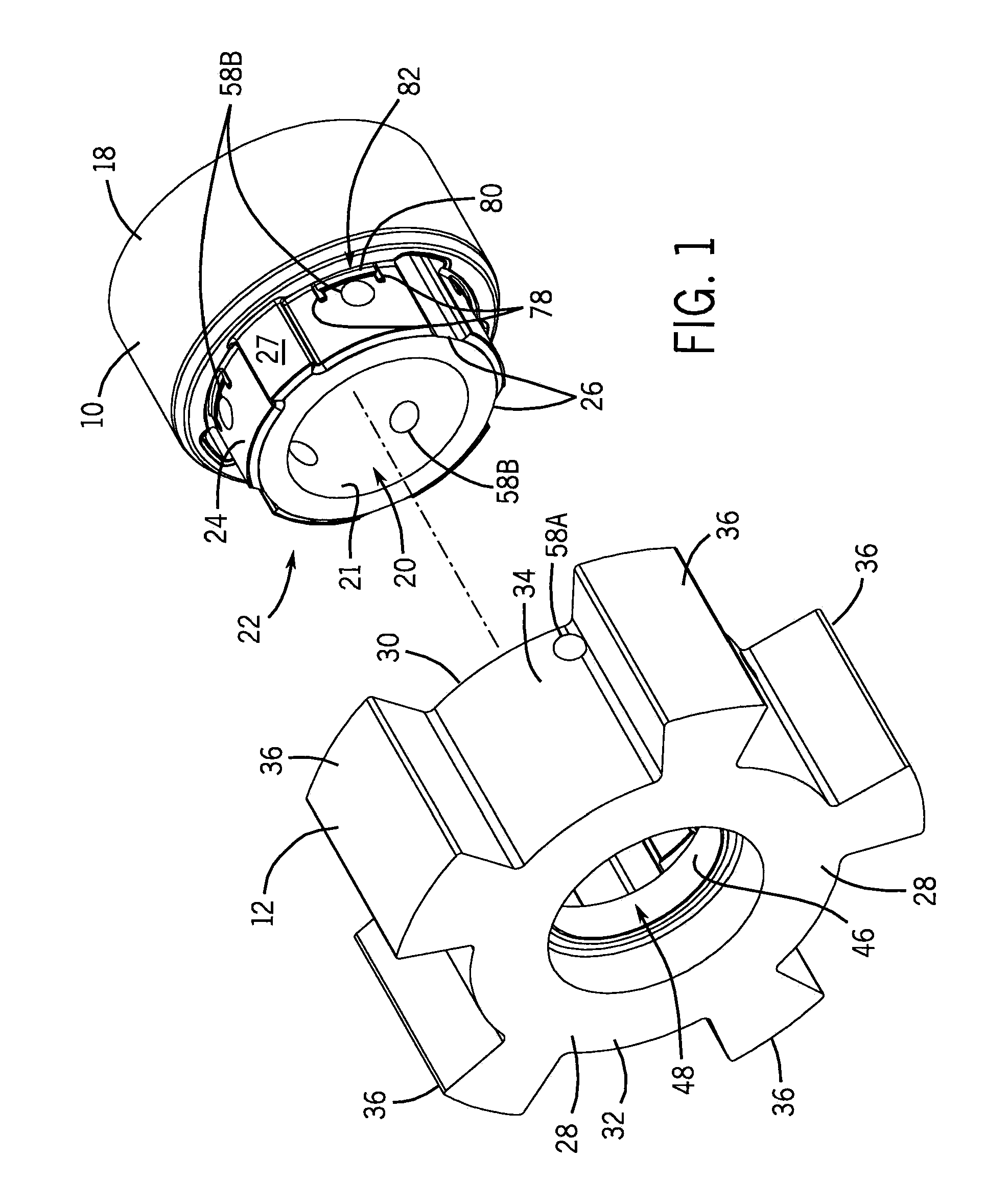
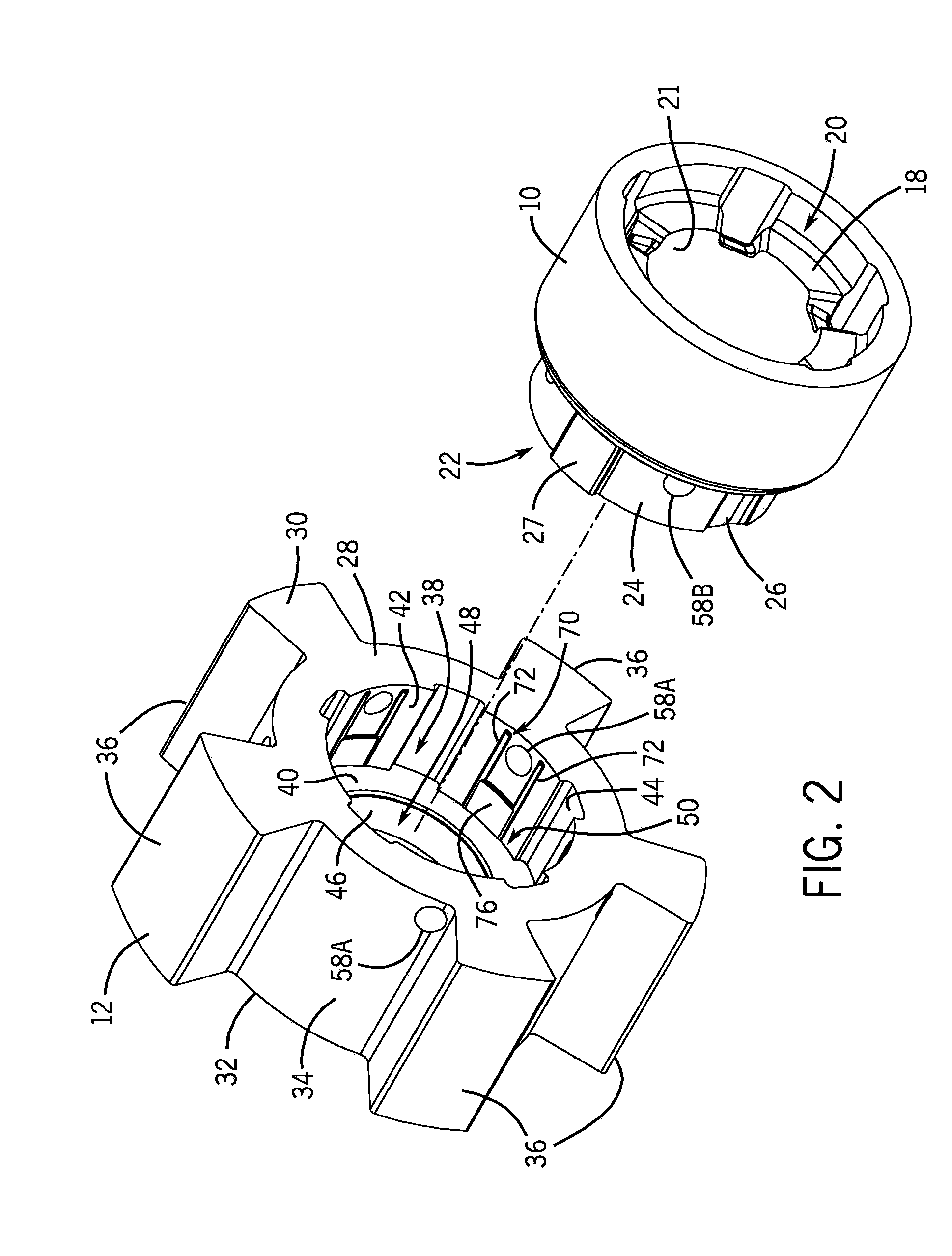
[0020]Referring first to FIGS. 1-2, a blank adaptor 10 and a rotor 12 are shown that can be adhesively joined to one another to form a rotor assembly 14 which undergoes finishing operations to form a finished rotor assembly. The adaptor 10 and the rotor 12 are both formed using powder metallurgical processes. Typically, this includes uniaxially compacting a powder metal and binder material in a tool and die set to form a powder metal preform and then sintering the powder metal preform to form a sintered part. Other steps known to those skilled in the art may also be used during this forming process including, but not limited to, burning off some of the binder material prior to sintering to reduce carbon content, forging the sintered part, coining the sintered part, heat treating the sintered part, and the like. The hole 58, made up of holes 58A and 58B would typically not be formed during compaction or sintering, but would typically be drilled either after sintering or after both pa...


PUM

PropertyMeasurementUnit
Diameteraaaaaaaaaa
Strengthaaaaaaaaaa
Heataaaaaaaaaa

Abstract

A method of joining multiple powder metal components to form a powder metal component assembly using an adhesive is disclosed. By machining at least one of the powder metal components prior to the adhesive joining, otherwise difficult to machine features can be more easily machined for less cost and at higher production rates. Unlike high temperature joining techniques, the adhesive joins the powder metal components at room temperature. This room temperature adhesive joining eliminates the thermal distortions in pre-joined machined features common to high temperature joining techniques such as brazing or welding that bring these features out of specification during joining.

Description

CROSS-REFERENCE TO RELATED APPLICATION[0001]This claims the benefit of U.S. Provisional Patent Application No. 61 / 175,154 filed May 4, 2009.STATEMENT CONCERNING FEDERALLY SPONSORED RESEARCH OR DEVELOPMENT[0002]Not applicable.FIELD OF THE INVENTION[0003]This invention relates to the joining of powder metal components. In particular, this invention relates to the joining of power metal components, such as rotors and adaptors, using adhesive.BACKGROUND OF THE INVENTION[0004]Powder metallurgy provides a cost effective way of producing components having relatively complex shapes at an acceptable cost. By compacting a powder metal into a preform and then sintering the preform into a sintered part, a porous body can be formed that is dimensionally close to the final desired component. Secondary operations, such as machining, grinding and the like can be used, and in some cases may be necessary, to bring the sintered part within dimensional specifications. The near net shape fabrication tec...

Claims


Application Information

Patent Timeline
IPC IPC(8): F01L1/34B32B37/02B32B37/12F16B7/00
CPCB22F5/008B22F5/08B22F5/106B22F7/062Y10T403/477F01L2103/00F16B11/008Y10T403/255F01L1/3442F01L2303/00
Inventor MALEN, GERALD MICHAELCOSTANZO, TIMOTHYDONALDSON, IAN W.MANDEL, JOEL H.
Owner SKN SINTER METALS LLC (US)
Why Eureka
Try Eureka