
Solar tracker device

a tracker device and solar energy technology, applied in the direction of moving/orienting solar heat collectors, photovoltaics, sustainable buildings, etc., can solve the problems of mechanical and installation problems, adverse landscape impact, cost and efficiency drawbacks, etc., to increase the energy that can be converted into electricity, the effect of efficiently tracking the sun and cost-effectiv

Inactive Publication Date: 2012-05-31
AHARON OREN
View PDF1 Cites 4 Cited by
  • Summary
  • Abstract
  • Description
  • Claims
  • Application Information

AI Technical Summary

Benefits of technology

[0012]The focus of the invention is to provide a device having cost effective tracking elements to efficiently track the sun and increase the energy that can be converted into electricity. The invention is a simple and reliable system powered by relatively small electric motors for efficient radiation conversion using significantly less electrical power and fewer motors. The present tracker device lowers the overall system cost by reducing the number of motors in the system and optimizing the position of rotating axes.
[0013]The present invention addresses the problems of high cost of solar trackers by activating several panels or mirrors with one motor each panel rotating along its approximate center of mass, thus, in its optimal position. The particular mechanical technique enables synchronous movement in two axes for multiple panels arranged in rows and columns, thereby providing an improved tracker relative to the and will substantially free of prior art drawbacks.
[0014]It is an object of this invention to provide a solar tracker with improvements in terms of cost, complexity, limited angle, large dimensions, wind sensitivity and so on.

Problems solved by technology

Technologically, photovoltaic power systems are capable of providing energy for any purpose, their main drawback being cost and efficiency.
This tends to create various problems like wind effect, adverse landscape impact and mechanical and installation problems.
Large tracker systems typically are installed using cranes and require a massive foundation.
The foundation and motorized gimbals used have to withstand considerable force even at low wind velocities due to the sail effect created by the large area of mounted panels.
Even mild winds will cause large stability problems and effect total system accuracy.
Due to the large wind loads and the large mechanical moment of inertia the motors actuating the gimbals system are enormous to provide the necessary moments for system operation.
In addition, such large constructions produce an adverse effect on the landscape and are costly to mitigate.
Concentrators equipped with solar cells are still an evolving technology for increasing efficiency of collection but are not yet mature due the high cost involved in building efficient collectors and trackers.

Method used


Image

  • Solar tracker device
  • Solar tracker device
  • Solar tracker device

Examples


Embodiment Construction

[0020]Illustrative embodiments of the invention are described below. In the interest of clarity, not all features / components of an actual implementation are necessarily described.

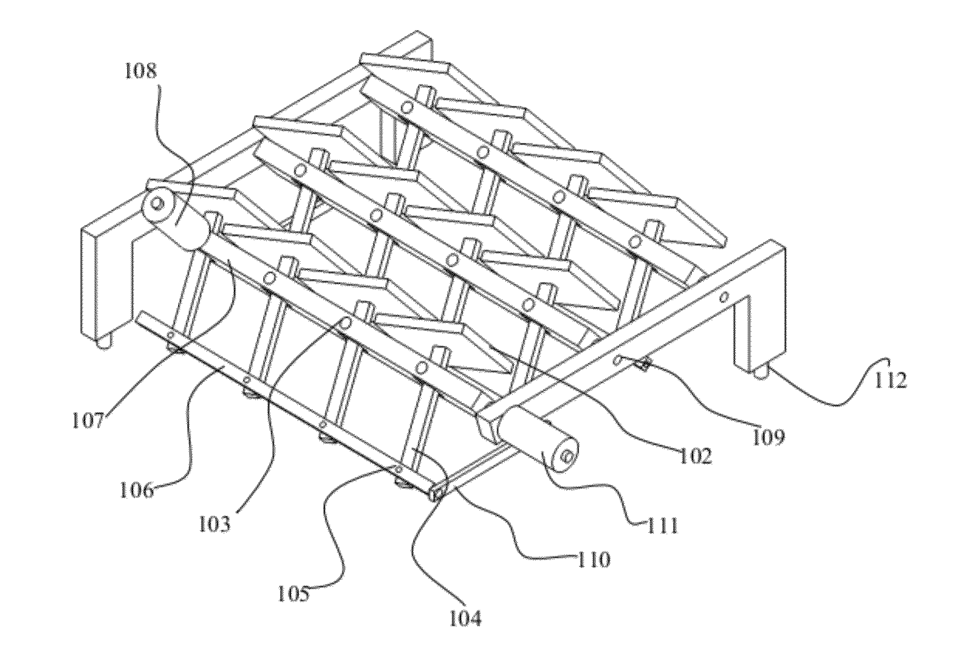
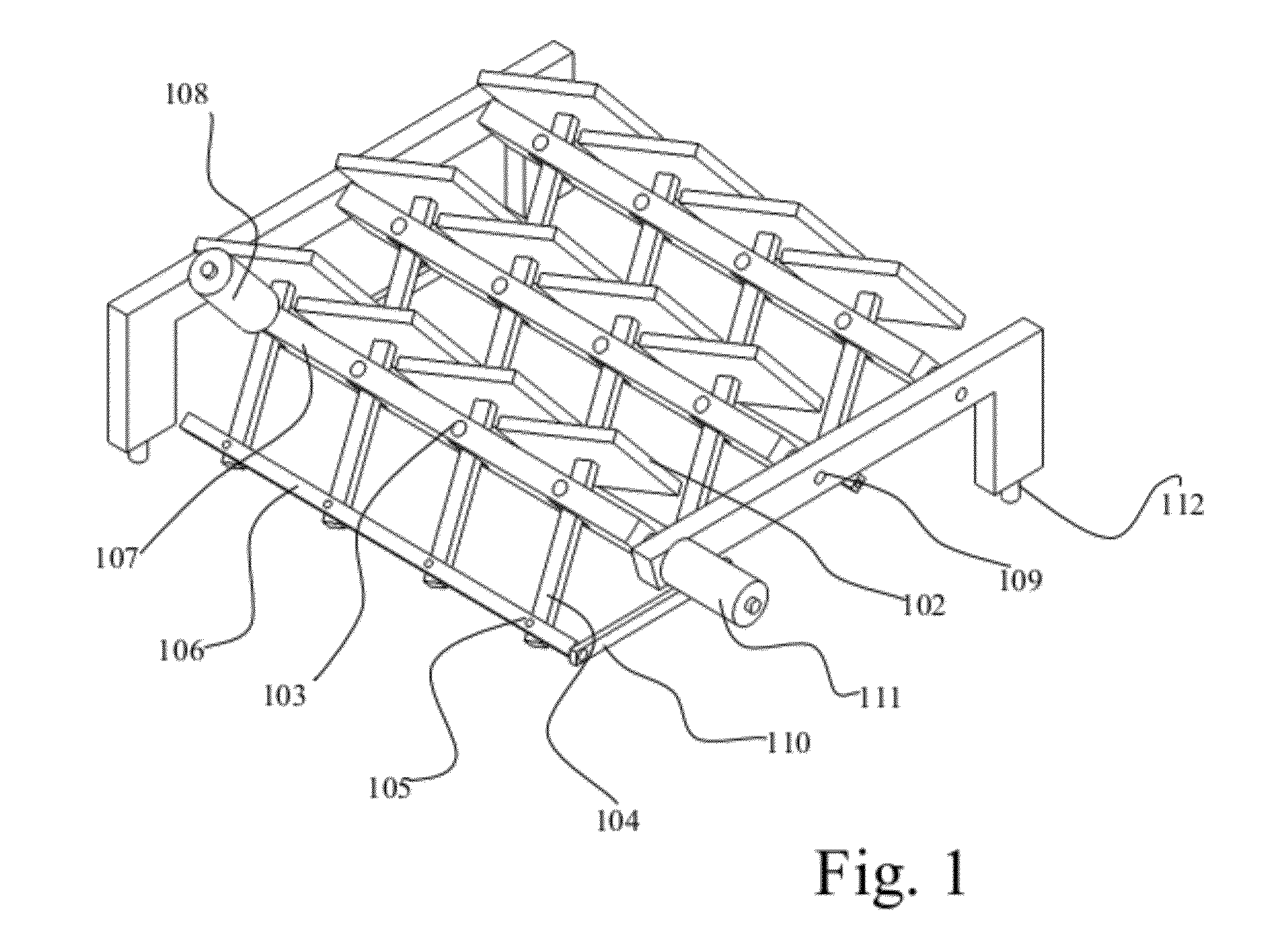
[0021]FIG. 1 shows a schematic layout of an embodiment of the present tracking device having multiple mirrors or panels 102 mounted in rows and columns. Each mirror or panel 102 is mounted on a mounting member 104, which is further mounted on a rotating axis 103. Mounting member 104 is further equipped with a parallel second axis of rotation 105. A mechanical link 106 creates a first four bar link by connecting all mounting members 104 in the same row and dictating synchronous parallel rotational movement in that row 107. A first motor actuator 108 allows controlling and aiming of the tracking device in one direction.

[0022]Multiple parallel rows are mounted on a frame, each free row free to rotate along its own axis 109. Axis 109 is substantially perpendicular to axis 103. Connecting members 110 connect eac...


PUM


Abstract

A solar tracker device based on a mechanical technique adapted to synchronously rotate mounted solar panels or mirrors along their approximate main axis, in one or two directions. The device enables building large solar fields with multiple panels or mirrors each rotated along its approximate location of its own main axis by single motor per axis.

Description

CROSS-REFERENCE TO RELATED PATENT APPLICATIONS[0001]This application claims priority from U.S. Provisional Patent Application No. 61 / 417,238, titled “Apparatus for a solar tracker device”, filed on Nov. 25, 2010, the entire contents of which are incorporated herein by reference.FIELD OF THE INVENTION[0002]The present invention relates to solar energy apparatus, in particular a tracker device therefor.BACKGROUND OF THE INVENTION[0003]A solar tracker is a device for orienting one or more solar panels or mirrors toward the sun, for example, photovoltaic panels. Tracking can substantially improve the amount of power produced by a solar energy system. Compared to the photovoltaic solar panels, trackers can be relatively inexpensive. This makes trackers particularly advantageous for photovoltaic systems using high-efficiency panels. The required accuracy of the solar tracker depends on the application.[0004]Photovoltaic devices are a leading technology to convert solar energy into electri...

Claims


Application Information

Patent Timeline
IPC IPC(8): H01L31/052F24J2/52
CPCF24J2/5424F24J2002/5455F24J2002/5468H02S20/00Y02E10/47Y02B10/10Y02B10/20Y02E10/52H02S20/32H02S20/22F24S30/455F24S2030/132F24S2030/136Y02E10/50
Inventor AHARON, OREN
Owner AHARON OREN
Learn More