Flexible nanocomposite generator and method for manufacturing the same

a generator and nanocomposite technology, applied in the direction of generator/motor, device material selection, coatings, etc., can solve the problems of large cost of nanogenerator manufacturing, difficult to achieve a large area, and complicated processes, and achieve simple manufacturing process, high efficiency, and large area

Active Publication Date: 2012-05-31
KOREA ADVANCED INST OF SCI & TECH
View PDF4 Cites 60 Cited by
  • Summary
  • Abstract
  • Description
  • Claims
  • Application Information

AI Technical Summary

Benefits of technology

[0006]An embodiment of the present invention is directed to provide a flexible nanocomposite generator that can be manufactured to have a large area with a simple manufacturing process while sh

Problems solved by technology

However, the present technologies require complicate processes and large cost in manufacturing of the nanogenerator and have difficulty

Method used


Image

  • Flexible nanocomposite generator and method for manufacturing the same
  • Flexible nanocomposite generator and method for manufacturing the same
  • Flexible nanocomposite generator and method for manufacturing the same

Examples


example 1

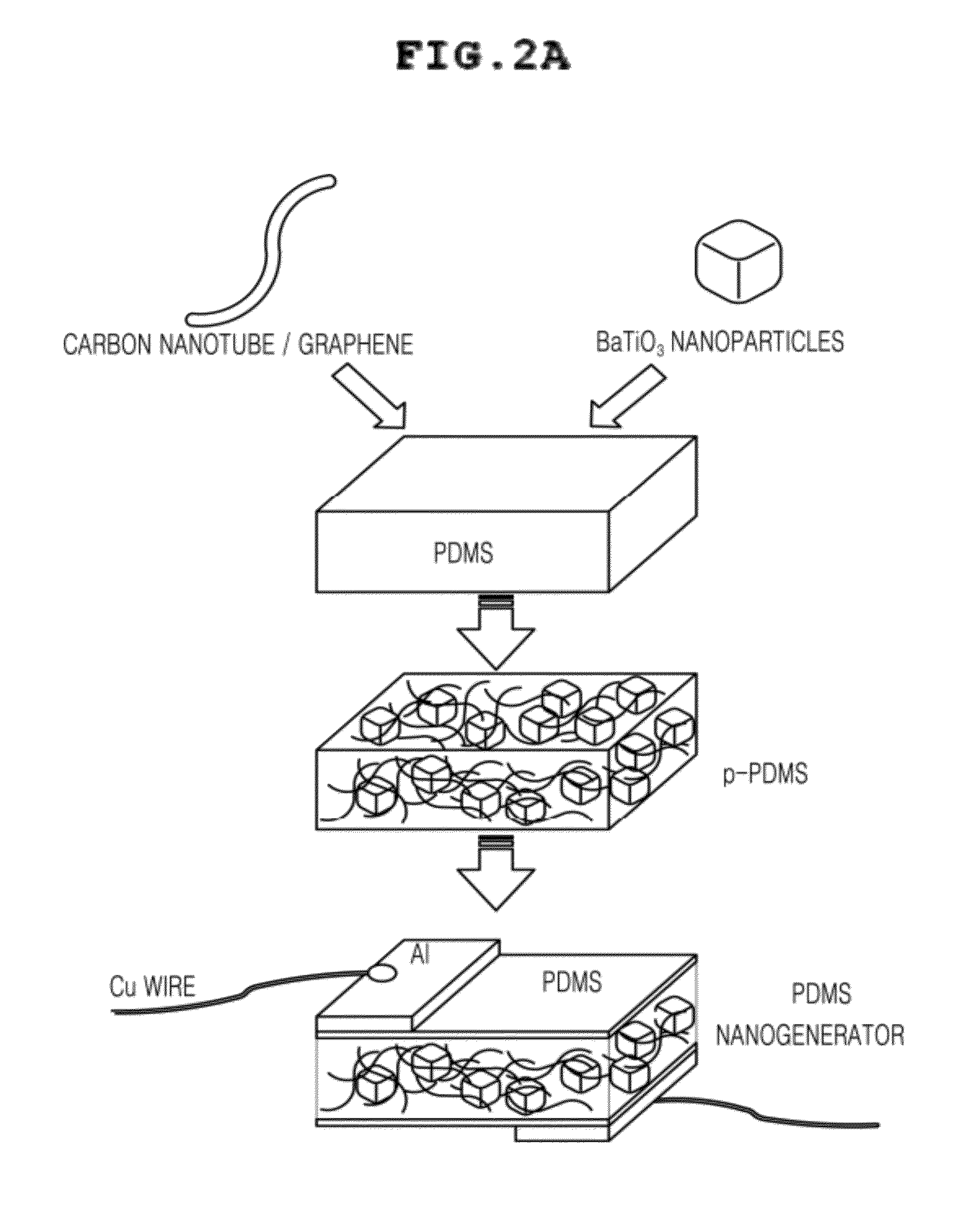
[0036]First, referring to FIG. 2A, carbon nanotubes were used as a carbon nanostructure and it can be seen that the carbon nanotubes have a sufficient conductive network in the particles of BTO mixed in the PDMS substrate after curing. The carbon nanotubes may have a single wall or a multi-wall. The carbon nanotubes had a diameter of 20 nm or less and the particles of BTO had diameters of 100 nm or less in an example of the present invention. That is, it is preferable that the diameter ratio of the carbon nanotubes and the particles of BTO constituting the network is 1:5 or less, such that the particles of BTO are effectively dispersed by the carbon nanotubes.

[0037]In detail, 0.3 g of multi-wall carbon nanotubes (Carbon Nano-material Technology) having a diameter of about 20 nm and a length of about 10 nm and 0.3 g of particles of BTO having sizes of about 100 nm which were acquired by a hydrothermal method, which is a method of manufacturing nanoparticles by dissolving a reaction m...

example 2

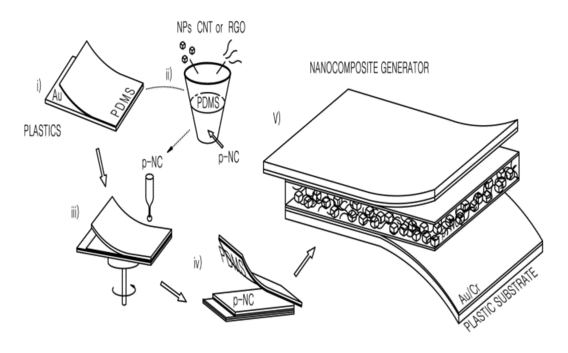
[0039]Referring to FIG. 2B, a nanocomposite material layer showing a piezoelectric property is formed by performing spin coating after mixing piezoelectric nanoparticles and carbon nanotubes in a PDMS solution, and then an electrode is formed on the nanocomposite material layer. According to an embodiment the electrode formed on the nanocomposite material may be an electrode composed of a plastic substrate-metal layer. The entire structure of the nanocomposite generator having this configuration is flexible.

[0040]FIG. 3 is an SEM cross-sectional image of the nanocomposite generator manufactured in accordance with FIG. 2B of the present invention. FIG. 3 shows that a piezoelectric layer having a thickness of about 200 μm is formed between two layers composed of a PDMS and a gold / chrome / plastic substrate.

[0041]FIG. 4 is an SEM cross-sectional image of the piezoelectric layer of the generator manufactured in accordance with FIG. 2B of the present invention. Referring to FIG. 4, it can ...


PUM


Abstract

There are provided a flexible nanocomposite generator and a method of manufacturing the same. A flexible nanocomposite generator according to the present invention includes a piezoelectric layer formed of a flexible matrix containing piezoelectric nanoparticles and carbon nanostructures; and electrode layers disposed on the upper and lower surfaces of both sides of the piezoelectric layer, in which according to a method for manufacturing a flexible nanocomposite generator according to the present invention and a flexible nanogenerator, it is possible to manufacture a flexible nanogenerator with a large area and a small thickness. Therefore, the nanogenerator may be used as a portion of a fiber or cloth. Accordingly, the nanogenerator according to the present invention generates power in accordance with bending of attached cloth, such that it is possible to continuously generate power in accordance with movement of a human body.

Description

CROSS-REFERENCE TO RELATED APPLICATION[0001]The present application claims priority of Korean patent application numbers 10-2010-0120111 filed on Nov. 30, 2010 and 10-2011-0087533 filed on Oct. 31, 2011, which are incorporated herein by reference in their entirety.BACKGROUND OF THE INVENTION[0002]The present invention relates to a flexible nanocomposite generator and a method for manufacturing the same, and more particularly, a flexible nanocomposite generator that can continuously generate power in accordance with movement of a human body and can also generate power by being used with a fiber, because power is generated by bending of a substrate, and a method for manufacturing the flexible nanocomposite generator.[0003]Recently, an energy harvest technology that converts an external energy source (for example, thermal energy, vibration generated from the nature, such as movement of animals or wind and waves, and mechanical energy) has been widely researched as an eco-friendly techn...

Claims


Application Information

Patent Timeline
IPC IPC(8): H02N2/18H01L41/22H01L41/18B82Y99/00
CPCB82Y30/00H01L41/183H01L41/113H01L41/37H10N30/30H10N30/852H10N30/092
Inventor LEE, KEON JAEPARK, KWI-ILKIM, DO KYUNGKIM, SANG OUKHWANG, GEON-TAE
Owner KOREA ADVANCED INST OF SCI & TECH
Why Eureka
Try Eureka