
Compensating for wander in ac coupling data interface

a data interface and compensation technology, applied in the field of integrated circuits, can solve problems such as inter-symbol interference, and achieve the effects of reducing the wander of the ac coupler

Active Publication Date: 2012-05-31
ADVANCED MICRO DEVICES INC
View PDF2 Cites 37 Cited by
  • Summary
  • Abstract
  • Description
  • Claims
  • Application Information

AI Technical Summary

Benefits of technology

The present patent describes various methods and structures to compensate for wander produced by AC couplers. The technical effect of this patent is to improve the accuracy and reliability of differential input signal processing by reducing wander of the AC coupler. This is achieved by adding a filtered differential reference signal to the high-pass-filtered differential input signal, which has a shifted common-mode voltage. The added reference signal can be created by shifting the common-mode voltage of the input signal and low-pass filtering it. This helps to improve the overall quality of the differential input signal processing.

Problems solved by technology

As a signal passes through a channel, the channel may introduce noise into the signal that causes inter-symbol interference.

Method used


Image

  • Compensating for wander in ac coupling data interface
  • Compensating for wander in ac coupling data interface
  • Compensating for wander in ac coupling data interface

Examples


Embodiment Construction

[0007]The present disclosure describes various embodiments of structures and methods to compensate for wander produced by AC couplers.

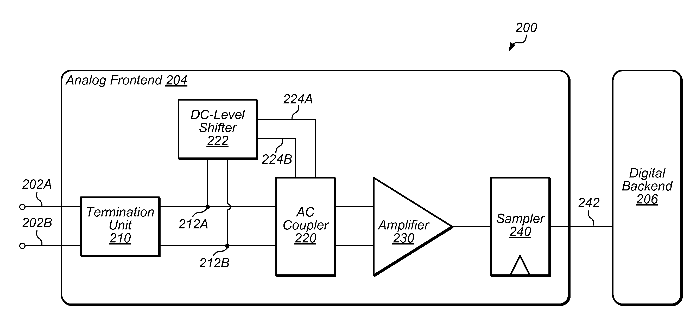
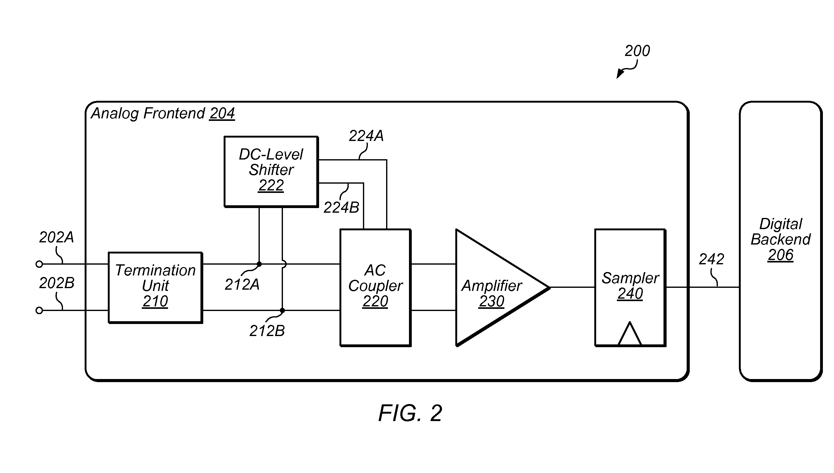
[0008]In one embodiment, an integrated circuit is disclosed. The integrated circuit includes an AC coupler and a DC-level shifter. The AC coupler is configured to receive a differential input signal at first and second nodes, and to shift a common-mode voltage of the differential input signal. The DC-level shifter is coupled to the first and second nodes, and is configured to reduce wander of the AC coupler. In some embodiments, the DC-level shifter is configured to supply a differential reference signal to the AC coupler. The DC-level shifter is configured to create the differential reference signal from the differential input signal at the first and second nodes by changing a common-mode voltage of the differential input signal.

[0009]In one embodiment, an apparatus is disclosed. The apparatus includes a receiver configured to use an AC coupler to hi...


PUM


Abstract

Techniques are disclosed relating to reducing wander created by AC couplers. In one embodiment, an integrated circuit is disclosed that includes an AC coupler and a DC-level shifter. The AC coupler is configured to receive a differential input signal at first and second nodes, and to shift a common-mode voltage of the differential input signal. The DC-level shifter is coupled to the first and second nodes, and configured to reduce wander of the AC coupler. In various embodiments, the DC-level shifter is configured to supply a differential reference signal to the AC coupler, and to create the differential reference signal from the differential input signal at the first and second nodes by changing a common-mode voltage of the differential input signal.

Description

RELATED APPLICATION[0001]The present application claims the benefit of priority to U.S. Provisional Application No. 61 / 417,749, filed Nov. 29, 2010, the disclosure of which is incorporated by reference herein in its entirety.BACKGROUND[0002]1. Technical Field[0003]This disclosure relates generally to integrated circuits, and, more specifically, to analog signal processing performed by receivers.[0004]2. Description of the Related Art[0005]Digital receivers typically have an analog frontend that is configured to process a received signal so that it can be sampled for use by a digital backend. As a signal passes through a channel, the channel may introduce noise into the signal that causes inter-symbol interference. Analog frontends may use a variety of techniques to reduce such interference to improve symbol recovery.[0006]In many instances, an analog frontend may amplify a received signal prior to sampling it to improve symbol recovery. In some instance, an analog frontend may use a...

Claims


Application Information

Patent Timeline
Patent Type & Authority Applications(United States)
IPC IPC(8): H03L5/00
CPCH03K3/356113H04B3/30
Inventor ZHUANG, JINGCHENG
Owner ADVANCED MICRO DEVICES INC
Learn More