Tomographic imaging method and tomographic imaging apparatus

a tomographic imaging and tomographic technology, applied in the field of tomographic imaging apparatus and tomographic imaging method, can solve the problems of image distortion, plurality of points cannot be measured under a desired condition, interference to occur between the return beam of the object to be inspected and the reference beam,

Inactive Publication Date: 2012-05-31
CANON KK
View PDF4 Cites 17 Cited by
  • Summary
  • Abstract
  • Description
  • Claims
  • Application Information

AI Technical Summary

Problems solved by technology

The OCT apparatus can measure cross-sections of an object to be inspected by splitting a low coherence beam into a reference beam and a measuring beam, irradiating the object to be inspected with the measuring beam, and causing interference to occur between a return beam from the object to be inspected and the reference beam.
However, in a case where the object to be inspected is a living body such as an eye, movement of the eye causes a problem of image distortion.
Specifically, the apparatus has various tolerances, and hence, in some cases, a plurality of points cannot be measured under a desired condition.
If a measurement is executed without any consideration of such cases, a desired area cannot be measured.

Method used


Image

  • Tomographic imaging method and tomographic imaging apparatus
  • Tomographic imaging method and tomographic imaging apparatus
  • Tomographic imaging method and tomographic imaging apparatus

Examples


first embodiment

[0024]Hereinbelow, a first embodiment of the present invention is described in detail with reference to the drawings. This embodiment is particularly effective in a case where movement of an object to be inspected can be ignored.

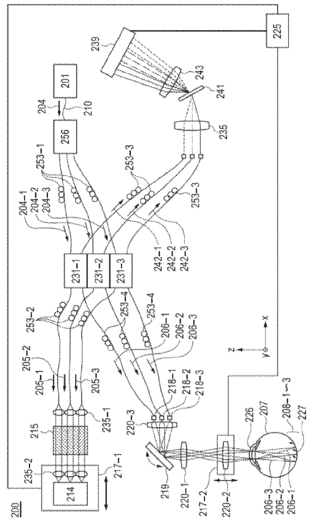
[0025]FIG. 2 is a diagram illustrating a configuration of a tomographic imaging apparatus using light according to this embodiment. As illustrated in FIG. 2, an optical coherence tomography (OCT) apparatus 200 forms a Michelson interferometer as a whole.

[0026](Optical System)

[0027]An outgoing beam 204 emitted from a light source 201 is guided by a single mode fiber 210 to enter an optical coupler 256, and is then split at the optical coupler 256 into outgoing beams 204-1 to 204-3, which pass through three optical paths of a first optical path, a second optical path, and a third optical path, respectively. Further, the three outgoing beams 204-1 to 204-3 pass through polarization controllers 253-1, and are then split at optical couplers 231-1 to 231-3 into re...

second embodiment

[0061]This embodiment is particularly effective in a case where a measurement is executed on an object to be inspected which moves during the measurement. In the tomographic image of each measurement area, B-scan images adjacent to each other within each measurement area are substantially continuous. On the other hand, B-scan images in the boundary area may be significantly shifted from each other. If a two-dimensional intensity image or a slow scan image is created in such a situation, in some cases, it is difficult to acquire a continuously connected image even after a correction is executed on the apparatus. Here, a difference from the first embodiment is particularly described.

[0062](Signal Processing)

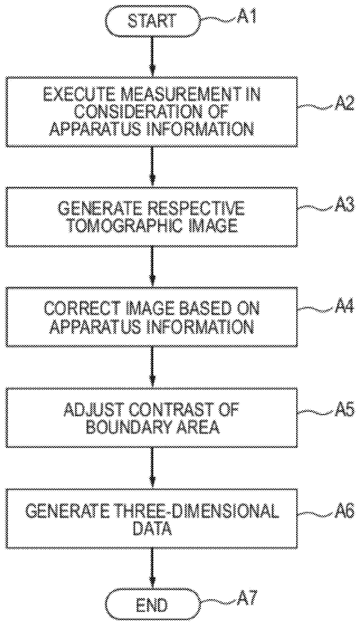
[0063]FIG. 5 illustrates a signal processing step according to a second embodiment of the present invention.

[0064]In the step A1, a measurement is started.

[0065]In the step A2, the measurement is started based on the apparatus information. It is to be understood that the measuremen...


PUM


Abstract

Provided is a tomographic imaging method, which acquires tomographic images of an object to be inspected, based on combined beams respectively acquired by combining reference beams and return beams acquired by irradiating the object to be inspected with a plurality of measuring beams. The tomographic imaging method includes a first step of acquiring the respective combined beams by reflecting information regarding the plurality of measuring beams which is stored in advance and irradiating the object to be inspected with the plurality of measuring beams, and a second step of generating the tomographic images based on the respective combined beams.

Description

BACKGROUND OF THE INVENTION[0001]1. Field of the Invention[0002]The present invention relates to a tomographic imaging apparatus and a tomographic imaging method, and more particularly, to a tomographic imaging method and a tomographic imaging apparatus which are used for ophthalmologic diagnosis and treatment.[0003]2. Description of the Related Art[0004]Currently, there are used various types of ophthalmologic apparatus using an optical instrument. Examples of the optical instrument for observing an eye include an anterior ocular segment photographing device, a fundus camera, and a confocal scanning laser ophthalmoscope (SLO). Of those, an optical tomographic imaging apparatus employing optical coherence tomography (OCT) which utilizes a low coherence beam is an apparatus capable of acquiring with a high resolution a tomographic image of an object to be inspected, and is thus becoming an indispensable apparatus as the ophthalmologic apparatus in outpatient treatment specialized in ...

Claims


Application Information

Patent Timeline
Patent Type & Authority Applications(United States)
IPC IPC(8): G01B9/02
CPCA61B3/102G01B9/02019G01B9/02091G01B9/02044G01B9/02028
Inventor SUEHIRA, NOBUHITOIWASE, YOSHIHIKO
Owner CANON KK
Why Eureka
Try Eureka