Method for operating a transmission device of a vehicle drivetrain

a transmission device and vehicle technology, applied in the direction of multiple ratio transmission, mechanical equipment, transportation and packaging, etc., can solve the problems of only being able to engage the interlocking shifting elements with or without additional structural synchronization devices comfortably, and achieve the effect of high level of shifting comfor

Active Publication Date: 2012-05-31
ZF FRIEDRICHSHAFEN AG
View PDF7 Cites 13 Cited by
  • Summary
  • Abstract
  • Description
  • Claims
  • Application Information

AI Technical Summary

Benefits of technology

[0007]Accordingly, the purpose of the present invention is to provide a method for operating a transmission device, by virtue of which gearshifts in the transmission devices that involve at least one inte...

Problems solved by technology

Since in a manner known per se such transmission devices can only be operated with unsatisfactory efficiencies because of drag losses that occur in the area of open frictional shifting elements, certain frictional shifting elements are replaced by interlocking shifting elements.
Disadvantageously, compared with frictional shifting elements, interlocking shifting elements with or without additional structural synchronization devices can only be engaged comfortably at very low speed differences, i.e. close to their synchronous rotational speed, and this impairs to an undesi...

Method used


Image

  • Method for operating a transmission device of a vehicle drivetrain
  • Method for operating a transmission device of a vehicle drivetrain
  • Method for operating a transmission device of a vehicle drivetrain

Examples


Embodiment Construction

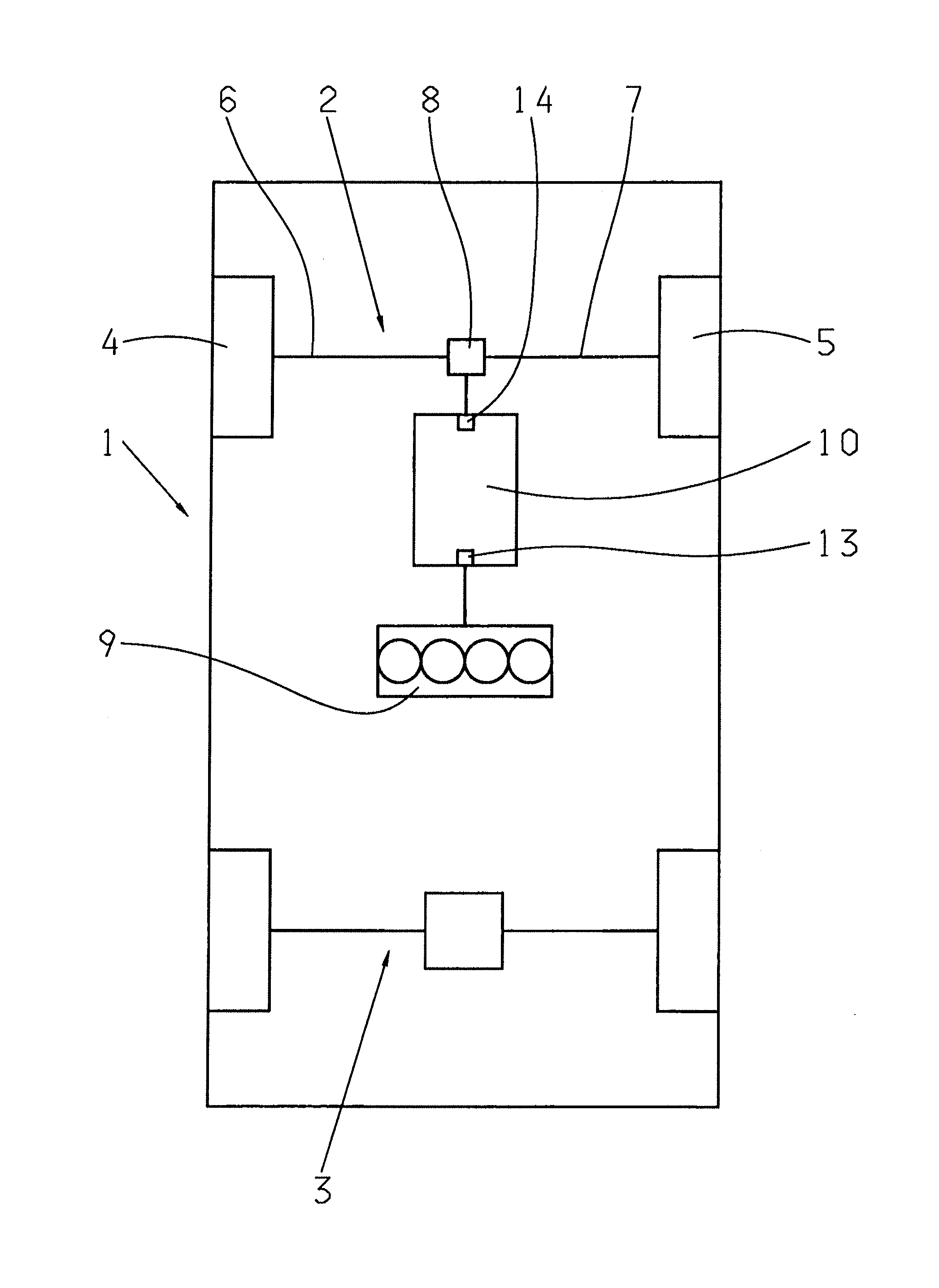
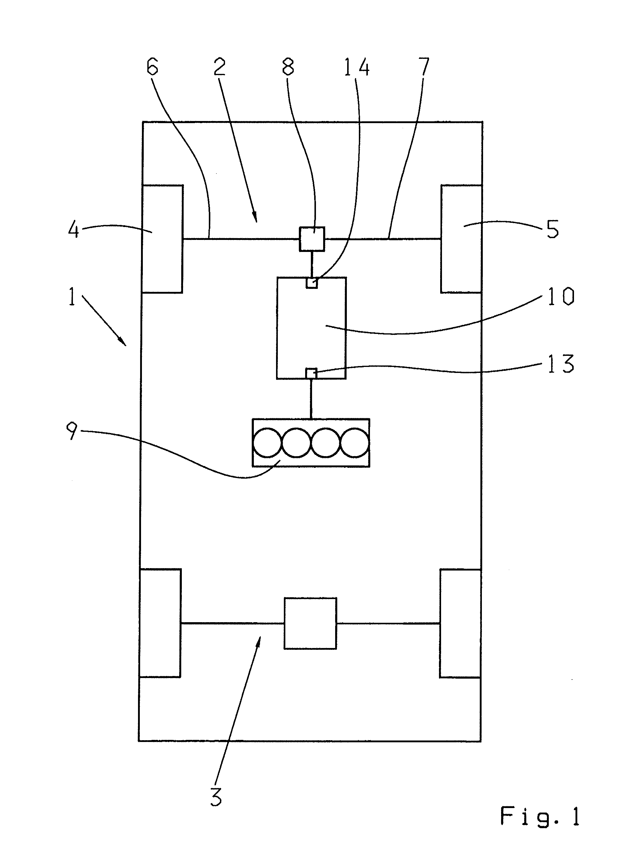
[0020]FIG. 1 shows a very schematic representation of a vehicle drive-train 1 with a first vehicle axle 2 and a second vehicle axle 3, the first vehicle axle 2 being a front axle of the vehicle and the second vehicle axle 3 being a rear axle of the vehicle. The first vehicle axle 2 has two drive wheels 4, 5 connected, via two drive shafts 6, 7, to a differential transmission unit 8. By means of the differential transmission unit 8, drive torque produced by a drive machine 9, in this case in the form of an internal combustion engine, is distributed in equal parts to the two drive wheels 4 and 5. In addition, between the drive machine 9 and the differential transmission unit 8, a transmission device 10 is provided, in this case in the form of an automatic transmission.

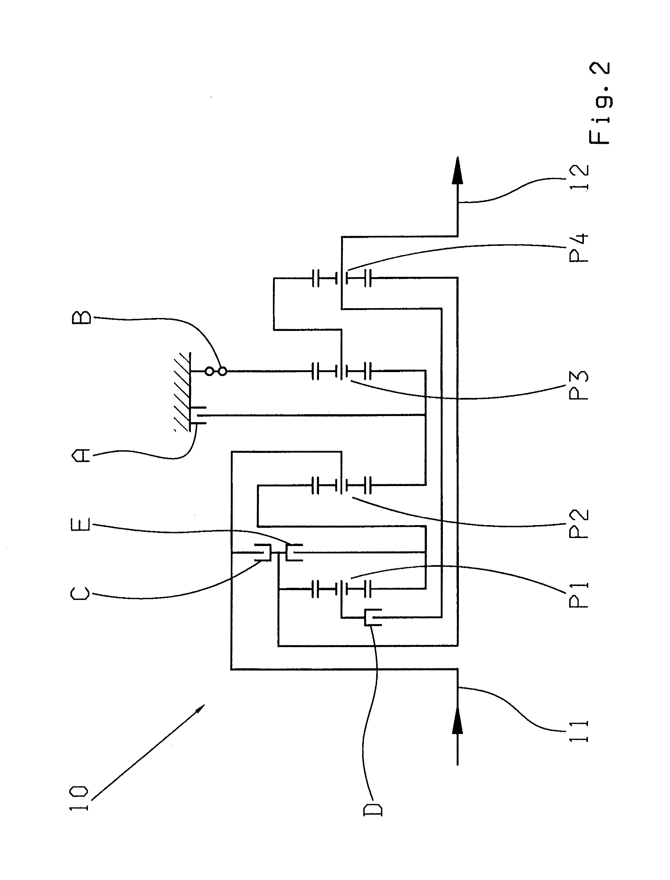
[0021]FIG. 2 shows a gearing layout of the transmission device 10, which is basically known from DE 10 2005 002 337 A1. The transmission device10 has a drive input shaft 11 and a drive output shaft 12, the latter connect...


PUM


Abstract

A method of operating a transmission of a vehicle drive-train that comprises frictional shifting elements and an interlocking shifting element. In the neutral operating condition of the transmission, and in the case of an operating condition variation of the vehicle drive-train in which, when it is required to establish the force flow in the transmission, the interlocking shifting element is to be changed from a disengaged to an engaged operating condition, by increasing the transmission capacities of at least two frictional shifting elements which have to be engaged for producing the force flow, a rotational speed difference in the area of the interlocking shifting element is determined, and a drive torque of a drive machine is adjusted to a level that brings the speed difference within a predefined range at which the interlocking shifting element is approximately synchronized and can therefore be engaged.

Description

[0001]This application is a National Stage completion of PCT / EP2010 / 060654 filed Jul. 22, 2010, which claims priority from German patent application serial no. 10 2009 028 305.6 filed Aug. 6, 2009.FIELD OF THE INVENTION [0002]The invention concerns a method for operating a transmission device of a vehicle drive-train.BACKGROUND OF THE INVENTION [0003]Transmission devices known per se and designed as automatic transmissions, such as a multi-stage transmission described for example in DE 10 2005 002 337 A1, are constructed in order to obtain various gear ratios with shifting elements by means of which in each case an applied torque can be transmitted by frictional means. When the engagement of a particular gear ratio has been called for, in each case at least one or more of the frictional shifting elements are disengaged from the force flow of a transmission device while at least one further frictional shifting element, or others, are engaged in the force flow of the transmission devi...

Claims


Application Information

Patent Timeline
IPC IPC(8): B60W10/04B60W10/10B60W10/02
CPCB60W10/06B60W10/115B60W30/188B60W2710/0666F16H61/0403F16H61/686Y10T477/6403F16H2200/2064F16H2200/006F16H2200/2012F16H2200/2043F16H2200/2094Y10T477/677F16H63/502F16H61/0437
Inventor CUPPERS, RUBENFUCHS, WERNERSCHMIDT, THILO
Owner ZF FRIEDRICHSHAFEN AG
Why Eureka
Try Eureka