
Automated treatment planning for radiation therapy

a technology for radiation therapy and treatment planning, applied in the field of treatment planning, can solve the problems of time-consuming and frustrating imrt planning, difficult to translate clinical requirements into cost functions, and complex process of imrt treatment planning

Inactive Publication Date: 2012-05-31
BOARD OF RGT THE UNIV OF TEXAS SYST
View PDF10 Cites 140 Cited by
  • Summary
  • Abstract
  • Description
  • Claims
  • Application Information

AI Technical Summary

Benefits of technology

[0026]The foregoing has outlined rather broadly the features and technical advantages of the present invention in order that the detailed description of the invention that follows may be better understood. Additional features and advantages of the invention will be described hereinafter which form the subject of the claims of the invention. It should be appreciated by those skilled in the art that the conception and specific embodiment disclosed may be readily utilized as a basis for modifying or designing other structures for carrying out the same purposes of the present invention. It should also be realized by those skilled in the art that such equivalent constructions do not depart from the spirit and scope of the invention as set forth in the appended claims. The novel features which are believed to be characteristic of the invention, both as to its organization and method of operation, together with further objects and advantages will be better understood from the following description when considered in connection with the accompanying figures. It is to be expressly understood, however, that each of the figures is provided for the purpose of illustration and description only and is not intended as a definition of the limits of the present invention.

Problems solved by technology

Although IMRT treatment planning methods have improved continuously over the years, IMRT treatment planning is still a complex process that depends strongly on the medical dosimetrist's experience (Schwarz 2009).
However, it is difficult to translate clinical requirements into a cost function and ‘steer’ the optimization toward the best result.
As a result, IMRT planning can be a time-consuming and frustrating task, and the quality of treatment plans with similar target dose prescriptions and normal tissue constraints will vary between treatment dosimetrists and institutions (Schwarz 2009).
Although IMRT can provide better outcomes for some cancers, the clinical benefits of this treatment can be compromised by sub-optimal treatment planning.
With the IMRT technique available to more and more community setting hospitals, it is very hard to ensure the plan quality.
After this study, Chung et. al. concluded that “our IMRT plans were not able to fully maximize the potential dosimetric gains of IMRT over 3DCRT”.
It can be imagined that it is almost impossible to let community hospital to perform those complex treatments if they started from scratch.

Method used


Image

  • Automated treatment planning for radiation therapy
  • Automated treatment planning for radiation therapy
  • Automated treatment planning for radiation therapy

Examples


example 1

AutoPlan for Use in Generating Treatment Plans for Lung Cancer Tumors

[0197]A. Treatment Plan Expert Database

[0198]A treatment plan expert database was created from 150 lung cancer cases previously designed by dosimetrists. In this database, the tumor position, beam angles (gantry, couch, collimator angles), and tumor sizes were recorded for each plan. The expert database served as the base for the beam angle selections of the beam angle algorithm.

[0199]B. Beam Angle Selection Based on Expert's Experience

[0200]Step 1 in FIG. 4 mainly involves the selection of coplanar and non-coplanar beam angles for each plan. The tumor position was defined in left, middle and right position of the lung. In FIG. 14, shows the frequency distribution of coplanar beam angles selected by the expert dosimetrists for treatment of lung cancer. The angle distribution for tumors located at the left side of lung is different from that used on the right side of the lung. For example, if the tumor is located on...

example 2

AutoPlan for Use in Generating Treatment Plans for Prostate Cancer Tumors

[0231]Eleven randomly selected prostate-cancer patients, each prescribed 76 Gy in 38 fractions, were studied. Each patient had a clinical plan that was generated by a dosimetrist using 8-beam IMRT with standard beam angles used in the treatment institution. A VMAT plan using two arcs (360-degree back and forth) was generated for each patient with autoplan algorithm. Also, a series of IMRT plans based on different numbers of beam angles were generated with the autoplan algorithm for each patient. For each patient, IMRT plan was started using autoplan with 8 beams with selected beam angles and the beam number was increased to 12, 16, and so on until the IMRT plan reach similar quality as the VMAT plan. All the autoplan-based IMRT plans used beam angles that one would consider would produce better organ-at-risk (OAR) sparing. Among the three usual OARs in prostate cancer, the femoral heads and the bladder are gene...

example 3

AutoPlan for Use in Generating Treatment Plans for Head and Neck Tumors

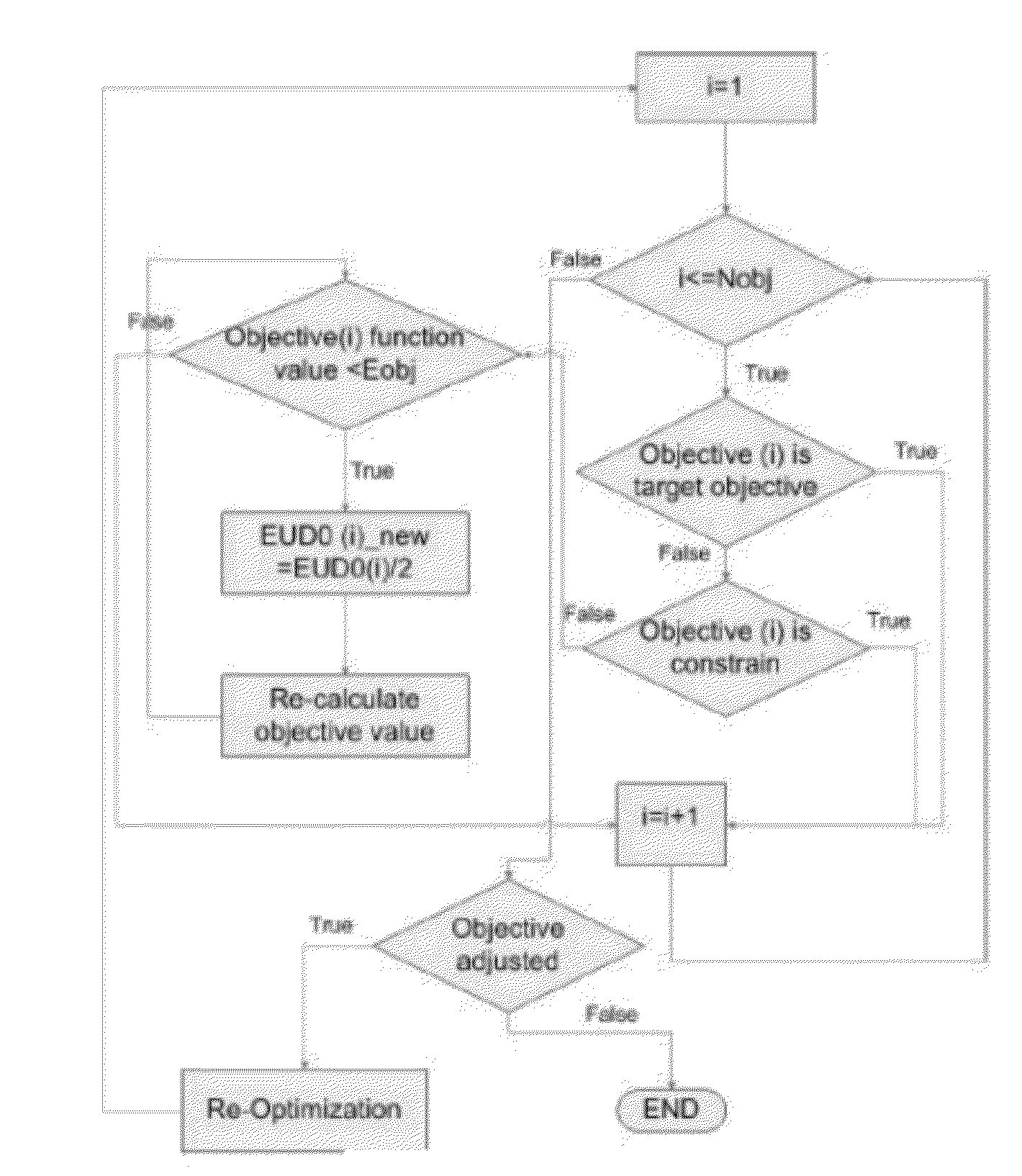
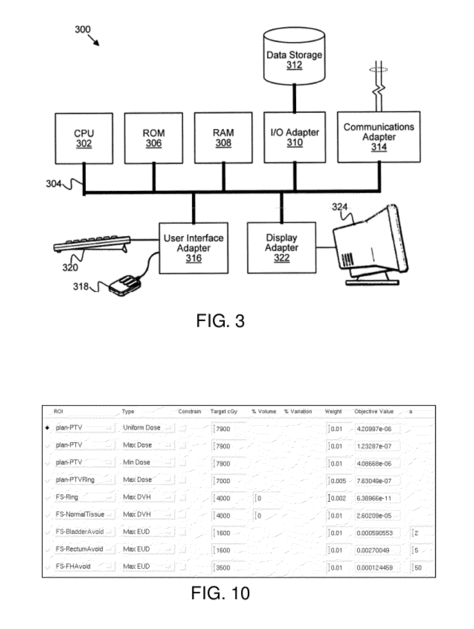
[0247]The AutoPlan algorithm for head-and-neck cancer follows a similar approach to that of prostate cancer. First, the algorithm automatically generates planning ROI structures based on physician-drawn contours; the newly generated structures involve modifications and additions to the original contours in order to improve the planning quality and efficiency. Radiation beams with pre-selected angles are then automatically configured and the inverse planning objectives with pre-defined parameters are loaded into the Pinnacle3 planning system. Optimization of the objectives is executed for the first round and then the PTV objective functions are evaluated. If all the PTV objectives are all well satisfied, increase the OAR objective weight or lower the OAR objective dose and continue optimization without resetting the beams; repeat this process until one or more PTV objectives are not well satisfied. In the last ste...


PUM


Abstract

This patent generally relates to developing treatment plans for use in external beam radiation therapy, and more particularly to a method, a system and a computer readable media that contains programming for the development of external beam radiation therapy treatment plans. Embodiments of the invention include (1) automatically setting beam angles based on a beam angle automation algorithm, (2) judiciously designing planning structures and (3) automatically adjusting the objectives of the objective function based on a parameter automation algorithm.

Description

CROSS-REFERENCE TO RELATED APPLICATIONS[0001]This application claims the benefit of U.S. Provisional Patent Application Ser. No. 61 / 374,485, filed Aug. 17, 2010, which is incorporated by reference herein in its entirety.STATEMENT REGARDING FEDERALLY SPONSORED RESEARCH OR DEVELOPMENT[0002]This invention was made with government support under Grant Number CA 16672 awarded the National Institutes of Health. The United States Government has certain rights in the invention.TECHNICAL FIELD[0003]The present invention relates generally to developing treatment plans for use in external beam radiation therapy, and more particularly to a method, a system and a computer readable media that contains programming for the development of external beam radiation therapy treatment plans, for treating patients in need of radiation therapy.BACKGROUND OF THE INVENTION[0004]Efforts to make radiotherapy treatment better, faster, and more cost effective have been underway since radiation was first used to t...

Claims


Application Information

Patent Timeline
Patent Type & Authority Applications(United States)
IPC IPC(8): A61N5/00
CPCA61N5/103A61N5/1047A61N2005/1041A61N5/1031A61N2005/1087
Inventor ZHANG, XIAODONGPAN, XIAONINGLI, YUPENGLI, XIAOQIANGMOHAN, RADHE
Owner BOARD OF RGT THE UNIV OF TEXAS SYST
Learn More