
Composite sole assembly

a sole assembly and composite technology, applied in the field of composite sole assembly, can solve the problems of increasing foot pressure and discomfort, affecting the comfort of shoes, so as to enhance forward roll and toe off, improve cushioning and comfort, and natural flex

Inactive Publication Date: 2012-06-07
BROWN SHOE
View PDF17 Cites 12 Cited by
  • Summary
  • Abstract
  • Description
  • Claims
  • Application Information

AI Technical Summary

Benefits of technology

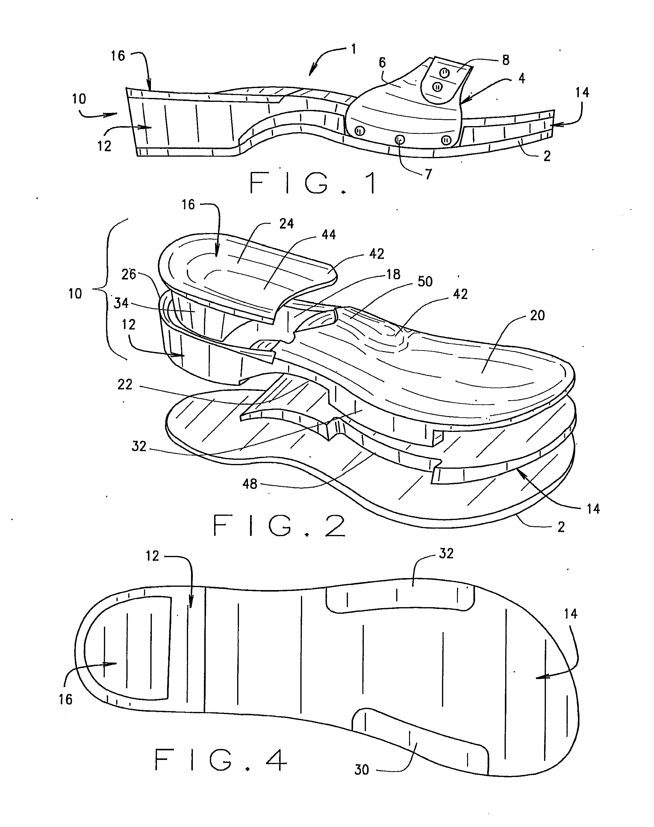
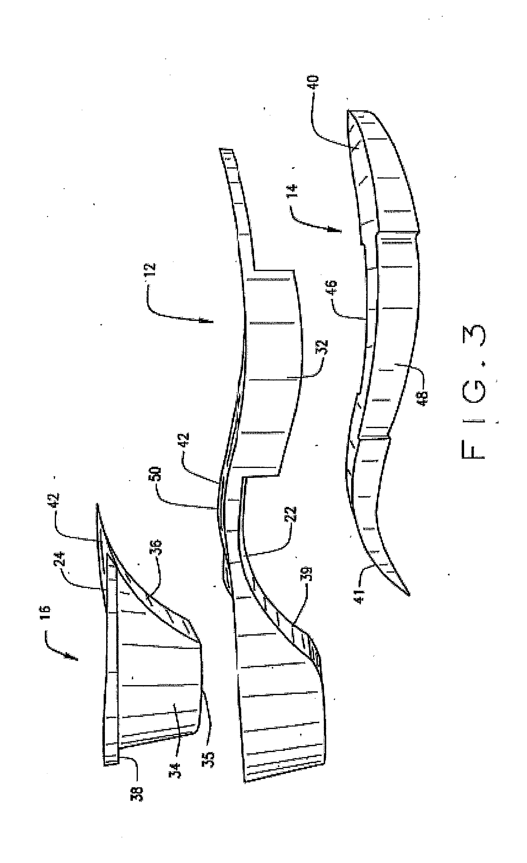
[0009]A sole assembly of the present invention includes, in one embodiment, a chassis made of a somewhat rigid material that integrates with a heel pad of foam material and a forefoot pad of foam material. The chassis includes two opposite posts or flanges for securing the upper, in some cases and, the outsole to the sole assembly. A heel pad is designed for the heel area to deliver improved cushioning and comfort. The heel pad is insertable into an opening in the chassis and covers the entire heel area from the center of the shank back and continues through the middle of the heel from top to bottom. A forefoot pad is positioned in the forefoot area under the chassis but on top of the outsole and extends the entire width of the chassis with the exception of two posts or flanges needed to secure the upper. The forefoot pad creates a pivot point that enables natural flexing and enhances forward roll and toe off as well as reduces forefoot strap stress. An upper is attached to the sole assembly via the posts or flanges of the chassis on the medial and lateral sides. The outsole is attached to the bottom of the chassis and the forefoot pad.
[0012]The chassis, combined with heel pad and forefoot pad, form the present composite sole assembly. The heel pad includes a generally concaved top surface, a curved side wall extending downwardly from the top surface and a tapered front wall. The heel pad fits into an opening in the chassis and mates with the interior front wall of such opening. A cushioning forefoot pad is positioned between the chassis and the outsole. Thus, when a person's foot steps-down onto the sole assembly of the present invention, the forefoot and heel pads which are constructed of a low density material provide cushioning and shock absorption to the wearer's foot and the chassis which is constructed of a more rigid material supports the wearer's foot.
[0014]When a foot is inserted into a sandal that houses the top surface of the present sole assembly, the recessed area serves to receive and locate the heel in a substantially concaved heel area, and the raised area portion supports the medial arch of a wearer's foot so that the top surface of the sole assembly contacts substantially the entire bottom surface of a wearer's foot. The raised area portion may be associated with one or both of the chassis and heel pad. The combination of a raised area under the medial arch and a recessed area immediately under the heel improves the distribution of pressure and comfort of shoes made in accordance with the teachings of the present invention.
[0015]While wearing the composite sandal of the present invention, a micro imbalance is created during toe-of that increases the range of motion during a person's stride or normal walking gait which enhances muscle activity and increases a wearer's focus on a natural gait. The forefoot pad also creates a pivot point that promotes forward roll and natural gait.

Problems solved by technology

Many conventional clog type sandals made of hard wood have a reputation of being popular yet uncomfortable because of their inflexibility.
These actions increase foot pressure and discomfort.
In addition, due to such sandals being made of wood, they are much heavier than other shoes in the market.
Thus, it is known that many users of such sandals experience foot pain when wearing these shoes immediately, and the majority of users experience such pain after as little as several hours of use.

Method used


Image

  • Composite sole assembly
  • Composite sole assembly
  • Composite sole assembly

Examples


Embodiment Construction

[0031]In the present invention, a composite sole assembly is provided to improve comfort and can be installed in any sandal type shoe. Although the present sole assembly will be disclosed in connection with a clog type sandal, those skilled in the art will recognize that the present sole assembly can be used with any sandal type shoe and with any footwear in general without departing from the spirit and scope of the present invention.

[0032]The reference numeral 1 designates generally a sandal type shoe construction as illustrated in FIG. 1. The shoe 1 includes an outsole 2, a sole assembly 10 mounted onto the outsole 2 and an upper 4 attached to the sole assembly 10. The upper 4 includes overlapping inner and outer flaps or straps 6 and 8 which are each respectively secured to the sole assembly 10 by any suitable fastening means 7 including, but not limited to, screws, buttons, snaps, laces, glue, cement or other adhesives, a hook and loop fastening means, or other suitable means. S...


PUM


Abstract

A composite sole assembly for attachment to an outsole of suitable material, the sole assembly including a chassis, a forefoot pad and a heel pad. The chassis includes an opening for receiving the heel pad and further includes two peripheral flanges for securing attachment with the shoe upper. A cushioning forefoot pad is positioned between the chassis and the outsole and between the two peripheral flanges and is formed of a soft cushioned foam material. The top surface of the chassis and the heel pad define a raised area in the midfoot region and a recessed area in the heel region of the assembly to better conform to the anatomical shape of a wearer's foot. The combination of the raised and recessed areas along with the positioning of the heel and forefoot pads improves comfort and provides for a better distribution of foot pressure during a normal gait.

Description

CROSS-REFERENCE TO RELATED APPLICATIONS[0001]This application claims priority to and incorporates herein by reference all disclosure in U.S. provisional patent application No. 61 / 370,072 entitled “COMPOSITE SOLE ASSEMBLY” filed Aug. 2, 2010.BACKGROUND OF INVENTION[0002]The present invention relates to a shoe sole construction with improved comfort and, more particularly, to a composite sole assembly for use with sandal type footwear designed to stimulate and exercise the foot during a natural walking gait.[0003]Sandals are an open type of outdoor footwear consisting of a sole held to the wearer's foot by straps or thongs passing over the instep and generally, but not always, around the ankle. Some traditional sandals, such as clogs, are made predominantly out of wood and, as such, are inflexible in that the entire sole construction is solid and does not flex as the foot normally does during a normal gait.[0004]Many conventional clog type sandals made of hard wood have a reputation o...

Claims


Application Information

Patent Timeline
Patent Type & Authority Applications(United States)
IPC IPC(8): A43B13/18A43B3/12
CPCA43B3/128A43B7/142A43B13/16A43B13/14A43B7/144
Inventor VATTES, DAVID L.BACON, STEVENGILLAM, JASON
Owner BROWN SHOE
Learn More