Combined baler/bale wrapper

a baler/bale wrapper and baler technology, applied in the field of baler/bale wrapper, can solve the problems of slow and inefficient integration of baler/bale wrapper, unacceptably high overall height of such baler, and relatively cumbersome integral baler/bale wrapper, so as to achieve efficient and smooth transfer, efficient construction of baler/bale wrapper, and convenient use.

Inactive Publication Date: 2012-06-07
WELMOUNT
View PDF11 Cites 20 Cited by
  • Summary
  • Abstract
  • Description
  • Claims
  • Application Information

AI Technical Summary

Benefits of technology

[0079]By urging the bale from the bale forming chamber in a generally upward direction which is between a generally vertical direction and a generally horizontal direction, a particularly efficient construction of a baler / bale wrapper is provided. By urging the bale from the bale forming chamber onto the bale wrapping means in this direction the bale can be transferred efficiently and smoothly onto the bale wrapping means. By urging the bale radially outwardly of the bale forming chamber, smooth efficient transfer of the bale is further accommodated. By urging the bale through an arc in a general upward direction between a general vertical direction and a general horizontal direction from the bale forming chamber onto the bale wrapping means provides for a particularly efficient construction of baler, and thus, particularly efficient construction of combined baler / bale wrapper.
[0080]The fact that the transfer means for transferring the bale from the baler to the bale wrapping means is arranged to move inwardly into the bale forming chamber and traverse through the bale forming chamber provides a further advantage of the invention, in that the bale can be urged in a general upward direction between a generally vertical direction and a generally horizontal direction from the bale forming chamber directly onto the bale wrapping means. This further facilitates in locating the bale wrapping means close to the baler, and thereby minimising the overall length of the combined baler / bale wrapper. A particularly important advantage of the invention is achieved when the transfer means for transferring the bale from the bale forming chamber to the bale wrapping means is provided by a moveable portion of the baler, and in particular, by a moveable lower portion of the baler. By pivoting the moveable lower portion of the baler so that the moveable lower portion of the baler is pivotal about the first pivot axis between the bale forming position and the discharge position provides a particularly efficient construction of baler / bale wrapper, which further enhances the efficiency and compactness of the baler / bale wrapper.
[0081]By providing an upper portion of the baler moveable between the bale forming position and the discharge position so that when the upper portion is in the discharge position an open mouth is defined to the bale forming chamber through which the bale is transferred from the bale forming chamber to the bale wrapping means, a particularly efficient construction of combined baler / bale wrapper is provided. By having the upper portion of the baler moveable upwardly from the bale forming position to the discharge position the upper portion of the baler when in the discharge position does not interfere in any way with a bale on the bale wrapping means, which would otherwise arises in known combined baler / bale wrappers where a portion of the baler is pivoted rearwardly for facilitating discharge of the bale from the bale forming chamber, if the bale wrapping means were not located at a distance from the baler. By virtue of the fact that the upper portion of the baler is moveable upwardly between the bale forming position and the discharge position, the bale wrapping means can be located significantly more closely to the baler than in baler / bale wrappers known heretofore, and this, thus, facilitates in direct transfer of the bale from the bale forming chamber to the bale wrapping means. Additionally, providing the moveable upper portion of the baler moveable in a generally upwardly direction facilitates in discharging the bale from the bale forming chamber in the generally upwardly outwardly direction, and in particular, facilitates in the discharge of the bale in a general upward direction between a generally vertical direction and a generally horizontal direction, and in particular, through an arc in such direction.
[0082]By pivotally mounting the moveable upper portion of the baler so that it is pivotal about the second pivot axis provides a particularly efficient construction which minimises the time required in operating the moveable upper portion and the moveable lower portion between the bale forming position and the discharge position for discharging a bale from the bale forming chamber to the bale wrapping means. Additionally, the time required for returning the moveable upper and lower portions of the baler from the discharge position to the bale forming position is likewise minimised, thereby providing for a relatively fast, efficient transfer of the bale from the bale forming chamber to the bale wrapping means and thus maximising the time during which the baler is operating to form bales.
[0083]Locating of the bale wrapping means close to the baler is further facilitated when the moveable upper portion is pivotally mounted about the second pivot axis, and is pivoted upwardly from the bale forming position to the discharge position, and the second pivot axis is located adjacent the circumferential periphery of the bale forming chamber and within an arc extending upwardly from a horizontal plane containing the main central axis of the bale forming chamber of not more than 60° and preferably not more than 30°, and in particular, when the second pivot axis is located at an angular distance from the said horizontal plane containing the main central axis of the bale forming chamber in the range of 10° to 15°.

Problems solved by technology

In general, integral baler / bale wrappers are slow and inefficient.
Additionally, due to the fact that the bale forming chamber must be split in order to allow wrapping of the bale to take place therein, an upper segment of the bale forming chamber is raised a relatively significant height from a lower segment in which the bale is rotated during wrapping, and thus, the overall height of such balers tends to be unacceptably high, and as such, such integral baler / bale wrappers tend to be relatively cumbersome.
Such transfer mechanisms tend to be cumbersome and inefficient.
Because of this, considerable time is lost during transfer of the bale from the baler to the bale wrapper.
Otherwise, in many cases it is not possible to return the transfer mechanism to the lower position with the tailgate of the baler in the closed position.
This, thus, significantly slows down the operation of such combined baler / bale wrappers.
A further disadvantage of combination baler / bale wrappers is that by virtue of the fact that a separate transfer mechanism is required for transferring the bale from the baler to the bale wrapper space is required between the baler and the bale wrapper for accommodating such transfer mechanism, and this, thus, tends to increase the overall length of combination baler / bale wrappers.
A further disadvantage of combination baler / bale wrappers is that in general, it is difficult to match the wrapping speed of the bale wrapper to the forming speed of the baler, and in general, the speed at which the bales are formed is significantly higher than the speed at which the bales are wrapped.
This, thus leads to inefficiencies in that either the baler must be operated at a speed lower than its capability, or alternatively, must be allowed to idle between the forming of each bale to allow time for wrapping of the formed bale.
A still further disadvantage of combined baler / bale wrappers known heretofore is that the transfer means for transferring a formed bale from the baler to the bale wrapper is in many cases incapable of transferring the formed bale to the bale wrapper during downhill operation of the baler / bale wrapper.
Thus, in practice, such baler / bale wrappers known heretofore in many cases are unsuitable for use in hilly areas.
Accordingly, this baler / bale wrapper tends to be relatively inefficient, in that a bale cannot be formed by the baler / bale wrapper while another bale is being wrapped.
Thus, this baler / bale wrapper tends to be inefficient.
This baler / bale wrapper would tend to be relatively complex, and by virtue of the fact that the wrapping table of the bale wrapper must be moved backwardly and forwardly between the baler and the bale wrapper would be subject to failure, and require relatively high maintenance.
Furthermore, the baler / bale wrapper would tend to be relatively inefficient.
By virtue of the fact that the baler must be moved rearwardly and forwardly on the platform, this baler / bale wrapper would be relatively complex and would tend to require significant maintenance.
Additionally, this type of baler / bale wrapper would tend to be relatively inefficient.

Method used


Image

  • Combined baler/bale wrapper
  • Combined baler/bale wrapper
  • Combined baler/bale wrapper

Examples


Embodiment Construction

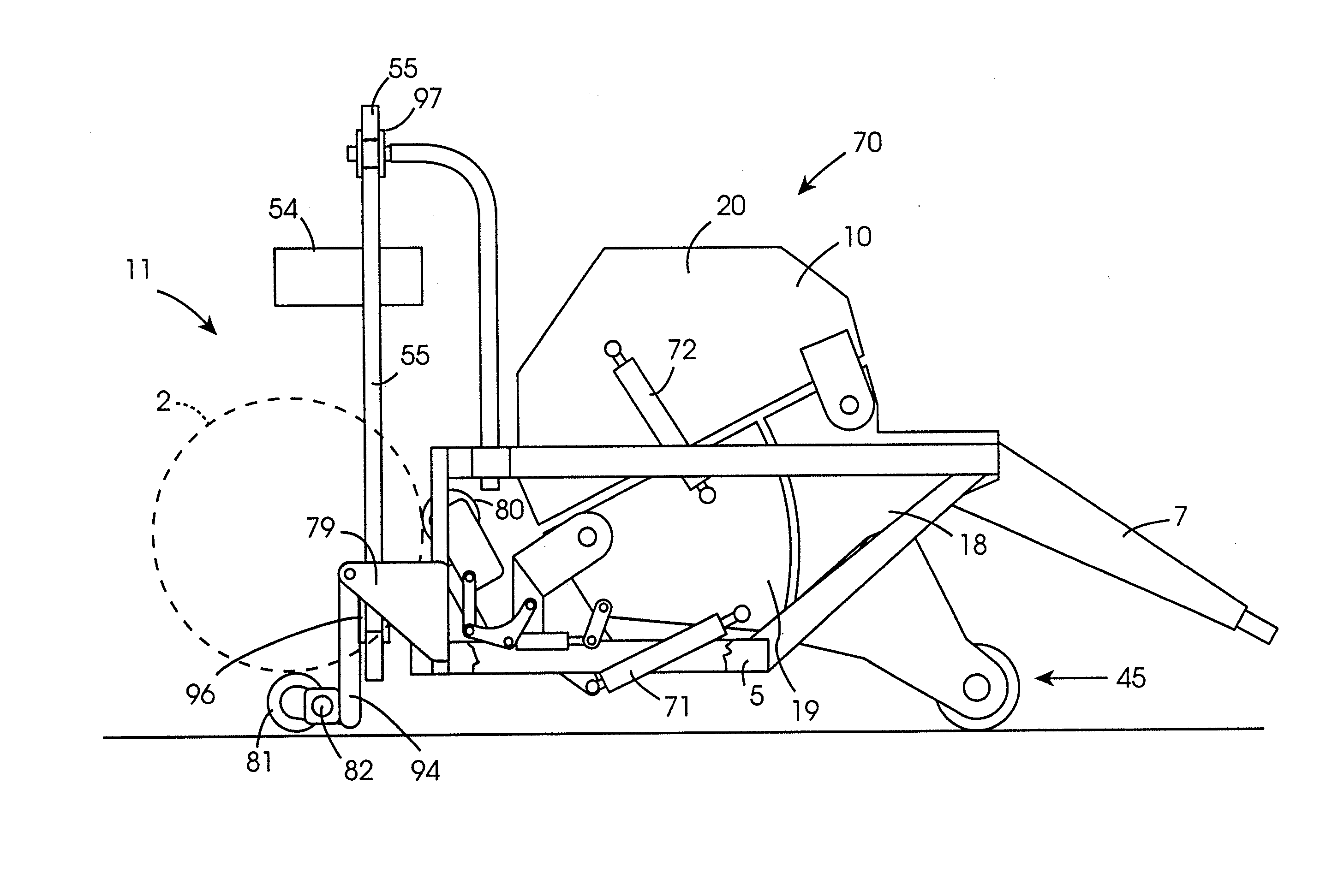
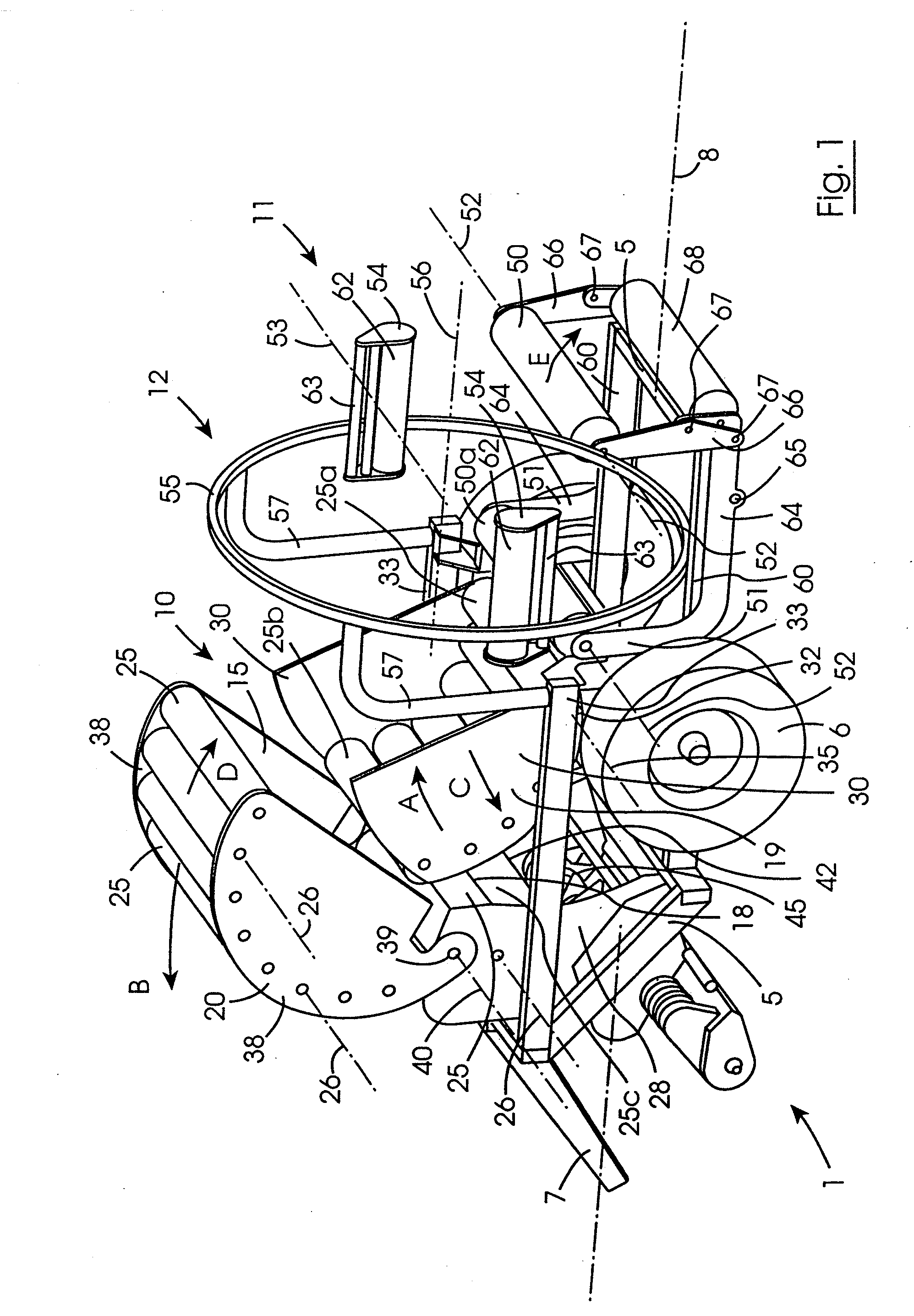
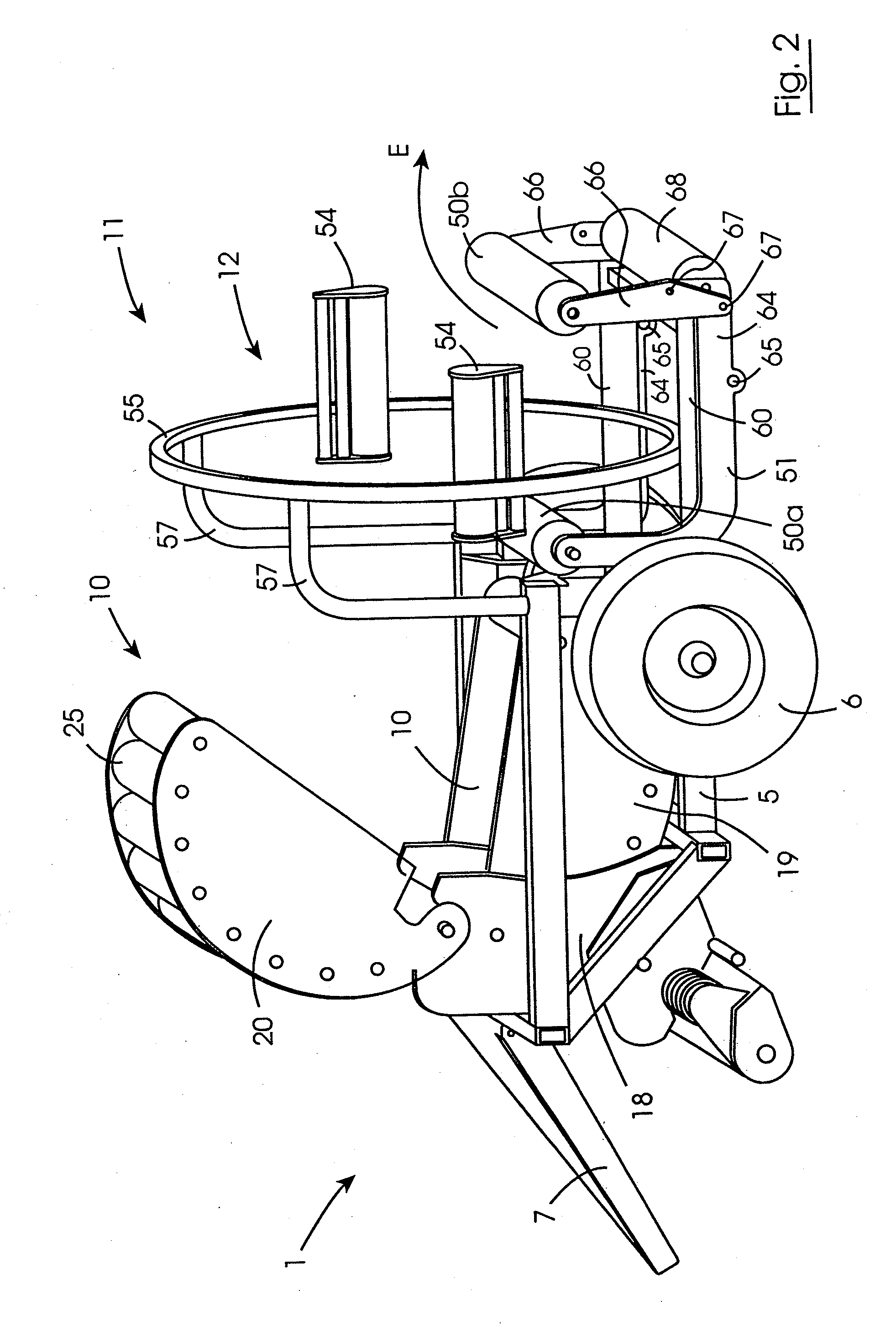
[0109]Referring to the drawings and initially to FIGS. 1 to 8 thereof there is illustrated a combined baler / bale wrapper according to the invention indicated generally by the reference numeral 1 for forming and wrapping a cylindrical bale of fodder material, typically, silage, the bale being of the type typically referred to as a round bale. In this embodiment of the invention the bale formed is of diameter approximately 1.25 metres and axial length of approximately 1.25 metres. A bale 2 is illustrated diagrammatically in FIGS. 3 to 6 being wrapped as will be described below. The baler / bale wrapper 1 is particularly suitable for towing behind a towing vehicle, such as, for example, a tractor, and is powered by the tractor, although the baler / bale wrapper could be self propelled and self powered. The baler / bale wrapper 1 comprises a chassis 5 which is carried on a pair of rotatably mounted ground engaging wheels 6. A framework 7 extending forwardly from the chassis 5 terminates in a ...


PUM


Abstract

A combined baler / bale wrapper (1) comprises a chassis (5) on which a baler (10) and a bale wrapper (11) are mounted. The baler (10) comprises a stationary segment (18), a lower segment (19) and an upper segment (20) which together define a bale forming chamber (15) within which a round bale (2) is formed. The lower segment (19) and the upper segment (20) are pivotal from a bale forming position (FIG. 5) to a discharge position (FIG. 1) for transferring a bale of the bale forming chamber (15) onto bale supporting rollers (50) of the bale wrapper (11). The bale supporting rollers (50) rotate the bale (2) about a first wrapping axis (53) while a carrier ring (55) simultaneously revolves a pair of wrapping material dispensers (54) about a second wrapping axis (56) for dispensing wrapping material onto the bale (2).

Description

[0001]This application is a divisional of U.S. patent application Ser. No. 10 / 472,399 filed Sep. 20, 2006, which is a national stage of PCT Application No. PCT / IE02 / 00037 filed Mar. 22, 2002, which claims benefit to Irish Patent Application No. S20010286 filed Mar. 22, 2001, and Irish Patent Application No. S20010678 filed Jul. 19, 2001. The above-noted applications are incorporated herein by reference in their entirety.BACKGROUND OF THE INVENTION[0002]The present invention relates to a combined baler / bale wrapper for forming and wrapping a cylindrical bale of material in a wrapping material.[0003]Baling of hay, straw, silage and other fibrous animal fodder crops is well known. Such crops may be formed into parallelepiped shaped bales or cylindrical bales. Parallelepiped bales may be relatively small bales which are typically referred to as rectangular bales, or relatively large bales which commonly are referred to as large square bales. Cylindrical bales are commonly referred to as...

Claims


Application Information

Patent Timeline
Patent Type & Authority Applications(United States)
IPC IPC(8): B65B17/00A01F15/00A01F15/07A01F15/08
CPCA01F15/071A01F15/0883A01F2015/0735A01F2015/074A01D39/005A01D59/00A01F15/0715B65B11/04B65B13/00A01F2015/0775A01F15/07B65B45/00
Inventor MCHALE, PADRAIC CHRISTOPHERMCHALE, MARTIN WILLIAMHEANEY, JAMES JOHNSHERIDAN, GERARD PATRICKO'CONNOR, PATRICK THOMASBIGGINS, JOHN PATRICK
Owner WELMOUNT
Why Eureka
Try Eureka