
Friction member for brake mechanism and camera shutter using the same

a technology of friction member and shutter, which is applied in the direction of cameras, instruments, transportation and packaging, etc., can solve the problems of extreme reduction of shutter durability and damage to friction members made of pets

Active Publication Date: 2012-06-07
BEIJING FUNATE INNOVATION TECH
View PDF20 Cites 8 Cited by
  • Summary
  • Abstract
  • Description
  • Claims
  • Application Information

AI Technical Summary

Benefits of technology

The patent text describes a friction member used for a brake mechanism and a camera shutter, which need to have high shutter speed and durability. The technical problem addressed is to provide a friction member that can overcome the shortcomings of existing friction members made of PET, which can be damaged in the braking process and decrease the initial braking performance. The solution is to provide a friction member with improved braking performance using a carbon nanotube polymer composite that includes a carbon nanotube structure and a polymer. The carbon nanotube structure is made of a plurality of carbon nanotubes that tightly combine with each other and define micropores. The carbon nanotube structure can be a single carbon nanotube film or multiple carbon nanotube films stacked on each other. The use of a carbon nanotube polymer composite helps to maintain the high mechanical strength and wearability of the friction member.

Problems solved by technology

However, the friction members made of PET can be damaged by the blade in the braking process with an acceleration of the shutter speed.
Thus, the initial braking performance cannot be maintained, and the shutter blade can be damaged in an early stage, or the durability of the shutter may be extremely decreased.

Method used


Image

  • Friction member for brake mechanism and camera shutter using the same
  • Friction member for brake mechanism and camera shutter using the same
  • Friction member for brake mechanism and camera shutter using the same

Examples


Embodiment Construction

[0020]The disclosure is illustrated by way of example and not by way of limitation in the figures of the accompanying drawings in which like references indicate similar elements. It should be noted that references to “an” or “one” embodiment in this disclosure are not necessarily to the same embodiment, and such references mean at least one.

[0021]A friction member is to provide a stable friction force for a brake lever in the brake mechanism in a camera shutter, thereby braking the brake lever. Therefore, the friction member should have high mechanical strength and wearability. The friction member can be any of number of desired shapes according to demands of space and any other requirements. The friction member can be a washer with a ring-shaped sheet structure. A thickness of the washer can be in a range from about 50 micrometers (μm) to about 500 μm. In one embodiment, the thickness of the washer can be in a range from about 50 μm to about 100 μm. The washer defines an inner diam...


PUM

PropertyMeasurementUnit
thicknessaaaaaaaaaa
thicknessaaaaaaaaaa
thicknessaaaaaaaaaa

Abstract

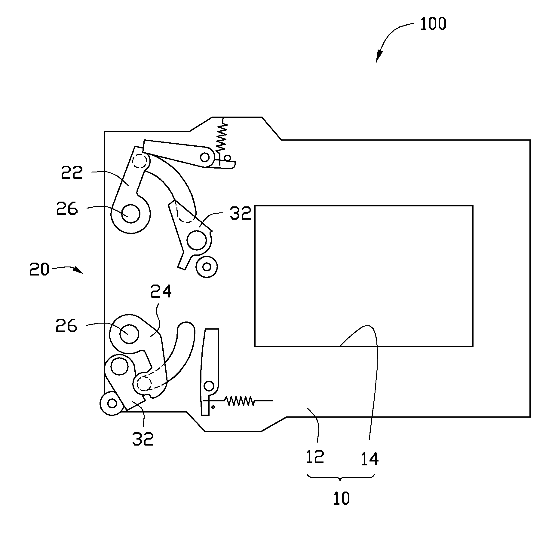
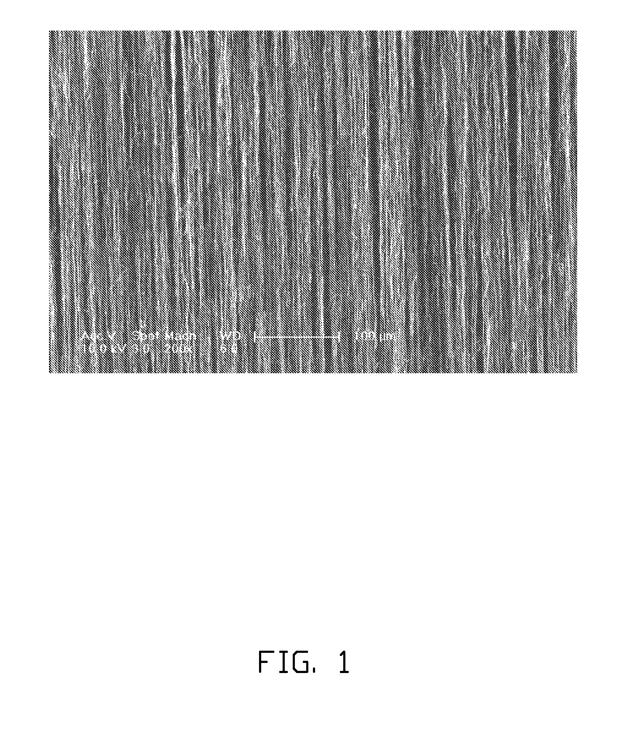
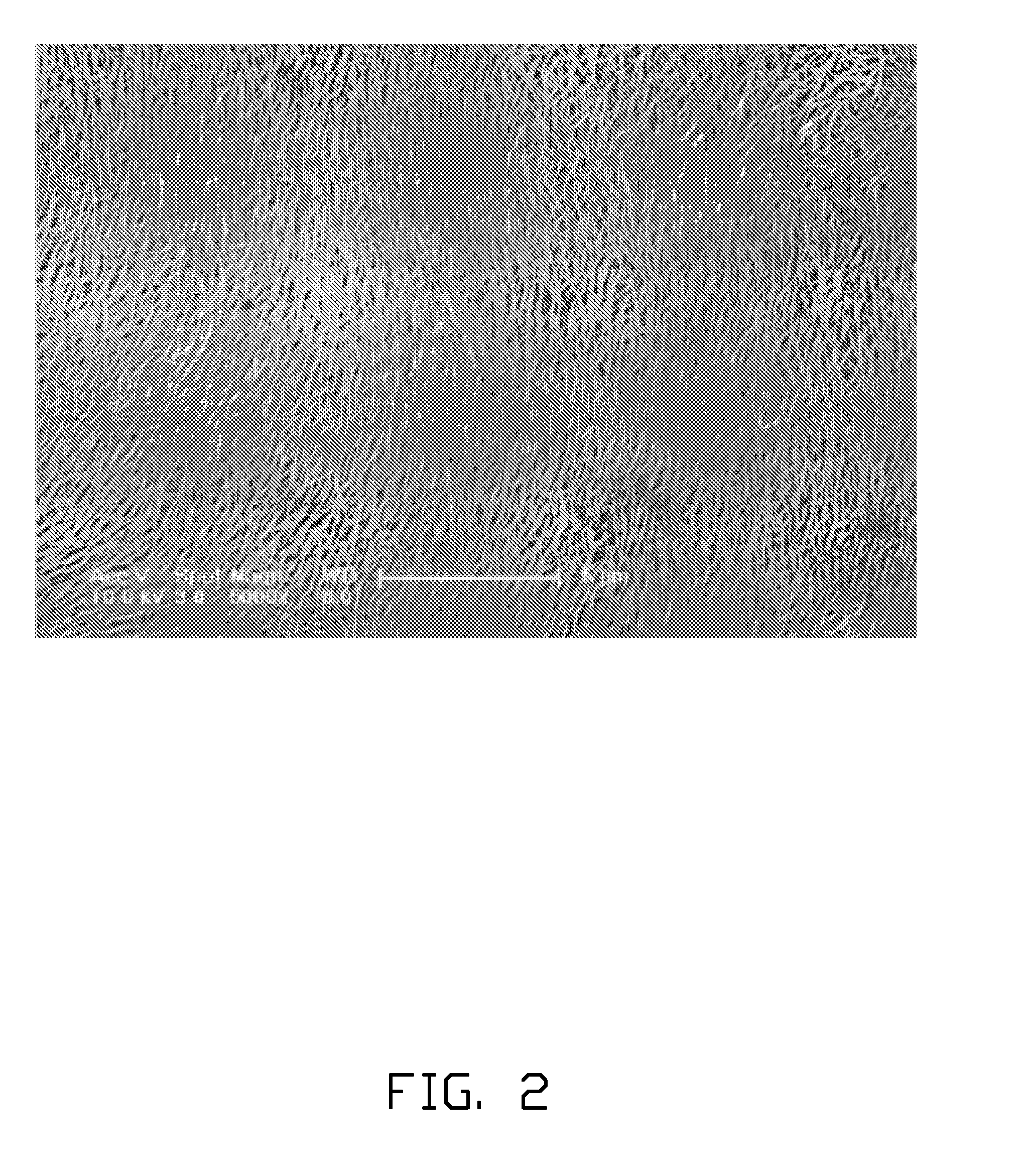
A friction member for a brake mechanism in a camera shutter is provided. The friction member includes at least two carbon nanotube composite layers stacked on each other, each carbon nanotube composite layer includes a polymer and a carbon nanotube structure including a number of carbon nanotubes substantially oriented along a same direction. An angle defined by the carbon nanotubes oriented along the same direction in adjacent carbon nanotube composite layers ranges from greater than 0 degrees, and less than or equal to 90 degrees. The camera shutter using the friction member is also provided. The camera shutter includes a brake mechanism and a drive mechanism including a blade driving lever having a moving path. The brake mechanism includes two abovementioned friction members and a brake lever clamped between the two friction members. The brake lever is located at a termination of the moving path to brake the blade driving lever.

Description

RELATED APPLICATIONS[0001]This application claims all benefits accruing under 35 U.S.C. §119 from China Patent Application No. 201010576901.7, filed on Dec. 7, 2010 in the China Intellectual Property Office, the disclosure of which is incorporated herein by reference.BACKGROUND[0002]1. Technical Field[0003]The present disclosure relates to friction members and camera shutters and, in particular, to a friction member used for a brake mechanism and a camera shutter using the same.[0004]2. Discussion of Related Art[0005]In order to obtain a camera shutter with high shutter speed and high durability, it is important to make shutter blades light and to improve the brake performance of a brake mechanism of the shutter.[0006]The braking force of the brake mechanism varies according to the thickness of friction members such as washers, and a set of friction members having proper thickness to calibrate the braking force. Polyethylene terephthalate (PET) is often used as a material of the fri...

Claims


Application Information

Patent Timeline
Patent Type & Authority Applications(United States)
IPC IPC(8): G03B9/08B32B5/12G03B17/56
CPCB82Y30/00G03B9/08G03B9/22Y10T428/24116G03B9/20Y10T428/24132G03B9/10
Inventor QIAN, LIWANG, YU-QUANFENG, CHENLIU, LIANG
Owner BEIJING FUNATE INNOVATION TECH
Learn More