Method and apparatus for predicting maintenance needs of a pump based at least partly on pump performance analysis

a technology of pump performance and prediction method, applied in the direction of positive displacement liquid engine, testing/monitoring control system, instruments, etc., can solve the problems of inability to achieve the effect of pump operation, theory does not support the shape of such a relation, and the pump cannot be practical, so as to achieve the effect of maximum pump operation efficiency, prolonging the life of the pump, and increasing the efficiency of the pump

Inactive Publication Date: 2012-06-07
CIDRA CORP SERVICES
View PDF8 Cites 17 Cited by
  • Summary
  • Abstract
  • Description
  • Claims
  • Application Information

AI Technical Summary

Benefits of technology

[0009]Predicting maintenance needs of a pump, including, e.g., large diameter slurry pumps, is a task that may be approached using a variety of tools and techniques. The present invention looks to optimize and maintain the trade-off that exists between increasing the efficiency of a pump, thereby reducing power usage, and decreasing maintenance needs and thus lowering non-productive down time and other costs related to performing the maintenance. In order to do so, the present invention provides a new way to monitor the decrease in pump efficiency with wear, such that it becomes feasible to adjust the maintenance interval to the rate of wear, and vice versa the wear rate to the maintenance interval, so that the total cost of ownership is substantially minimized. Adjusting the rate of wear in a pump, of course, can be accomplished by increasing or decreasing internal clearances using a predictable maintenance schedule based at least partly on historical data that is tracked over time.
[0010]For example, one way of tracking pump efficiency is to compare over time, the hydraulic power generated by the pump and the electric power consumed by the motor driving the pump. Assuming that bearings and seals are well maintained and lubricated where necessary the wear of these elements might be negligible compared to the wear of wetted pump parts subjected to abrasive internal flow. If this assumption holds, then the ratio of hydraulic to electric power can be a useful number or indicator to track as it will allow striking a balance between efficiency and pump wear so as to make the cost of operating the pump as low as possible.

Problems solved by technology

There is absolutely no hydraulic pump theory backing it up.
Theory only stipulates a relation between the head and the flow coefficient but theory does not predict the shape of such a relation.
Such a pump would not be practical because of the mechanical friction that the impeller would impart on the pump casing.
It is not in general possible to overcome this by interpolation on non-missing points as the intervals containing missing values can be rather long.
Such unphysical values may be measurement error but they may also be the result of a process condition that is not representative of normal operations.
Obviously this type of behaviour is not desired.
Yet, the efficiency curve shows an upward curving tail at high flow coefficients which is not possible in a real pump.
The entire spike around that period, which disturbs the downward trend of the pump efficiency which is otherwise visible is suspect.
It is possible that the current probe may have been replaced around that day and was not properly recalibrated until some days later.
Contrariwise, those events will be visible in all of the four plot and may thus be much harder to identify.
If those clearances increase due to wear there will be increased internal recirculation inside the pump which causes the pressure and discharge flow to be less than optimum.

Method used


Image

  • Method and apparatus for predicting maintenance needs of a pump based at least partly on pump performance analysis
  • Method and apparatus for predicting maintenance needs of a pump based at least partly on pump performance analysis
  • Method and apparatus for predicting maintenance needs of a pump based at least partly on pump performance analysis

Examples


Embodiment Construction

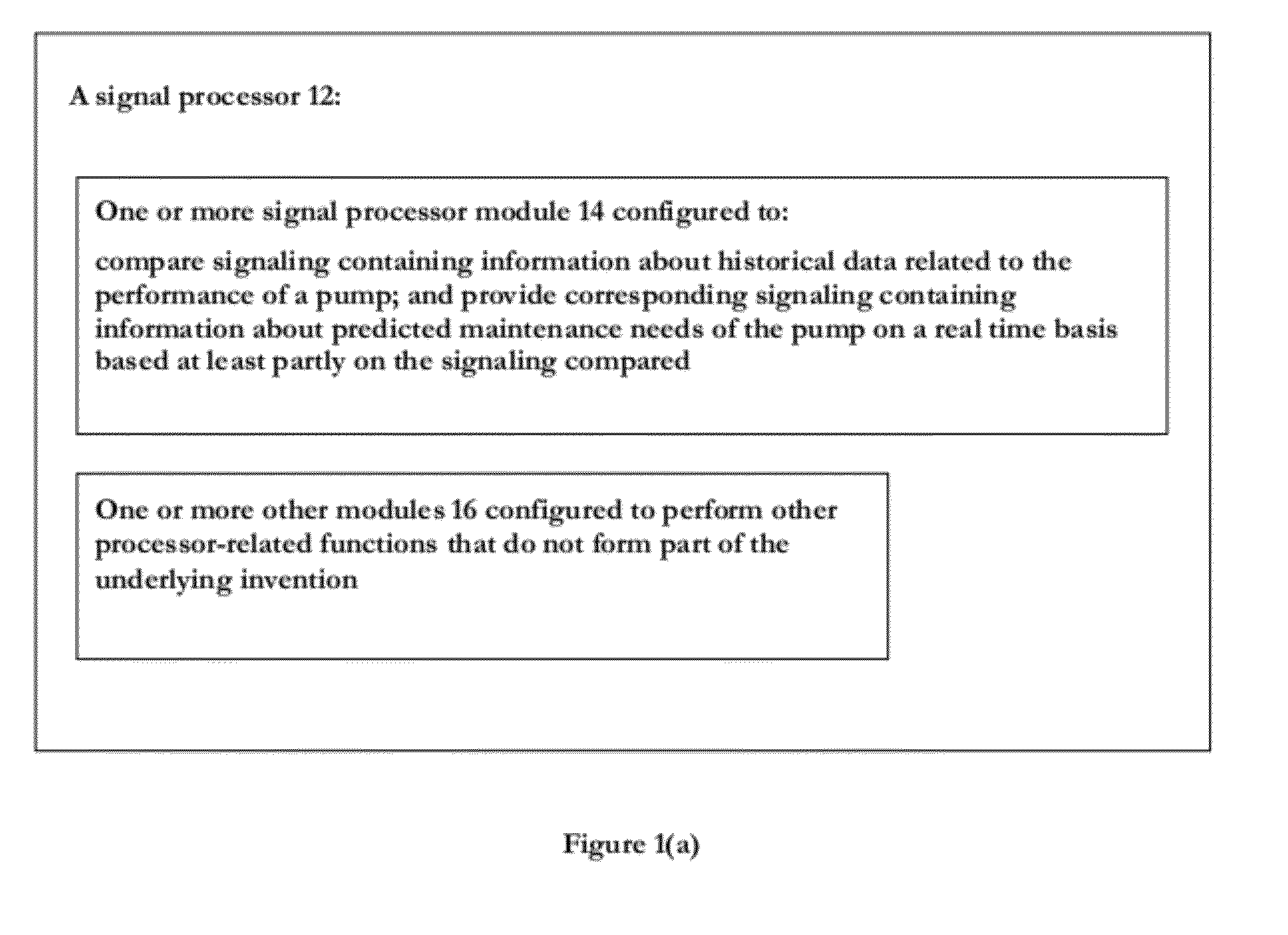
[0050]FIG. 1(a) shows a signal processor 12 comprising one or more signal processor modules 14 and one or more other modules 16. The one or more signal processor modules 12 is configured to compare signaling containing information about historical data related to the performance of a pump; and provide corresponding signaling containing information about predicted maintenance needs of the pump on a real time basis based at least partly on the signaling compared containing information about the historical data related to the performance of the pump. The one or more other modules 16 is configured to cooperate with the one or more signal processor modules 12 and perform other processor-related functions that do not form part of the underlying invention, including input / output functionality, memory functionality, etc.

[0051]By way of example, the one or more signal processor modules 12 may be configured to compare over time one signal containing information about the hydraulic power gener...


PUM


Abstract

A signal processor is provided comprising one or more signal processor modules configured to: compare signaling containing information about historical data related to the performance of a pump; and provide corresponding signaling containing information about predicted maintenance needs of the pump on a real time basis based at least partly on the signaling compared containing information about the historical data related to the performance of the pump. The one or more signal processor modules may be configured to compare over time the hydraulic power generated by the pump and electric power consumed by a motor driving the pump, including tracking a ratio of hydraulic to electric power. The one or more signal processor modules may be configured to predict maintenance needs based on an algorithm that takes into account a trade-off between the cost of power consumed by a motor driving the pump and the cost associated with the pump maintenance in order to substantially minimize the total cost of operating the pump.

Description

CROSS-REFERENCE TO RELATED APPLICATIONS[0001]This application claims benefit to provisional patent application Ser. No. 61 / 186,502, filed 12 Jun. 2009, which is hereby incorporated by reference in its entirety.BACKGROUND OF THE INVENTION[0002]1. Field of the Invention[0003]The field of the invention relates to a technique predicting maintenance needs of a pump, including large diameter slurry pumps.[0004]2. Description of Related Art[0005]Pumps need to be maintained during the course of their lifetime. Pumps that are well maintained have a tendency to operate longer and more efficiently than pumps that are not well maintained.[0006]By way of example, maintenance may be carried out to prolong the lifetime of a pump, or to increase the efficiency of the pump, or both. An example of lifetime prolonging maintenance is the dynamic balancing of impellers which reduces vibration and thereby increases the lifetime of a pump. An example of maintenance geared to increase efficiency is the rep...

Claims


Application Information

Patent Timeline
Patent Type & Authority Applications(United States)
IPC IPC(8): F04B49/00F04B51/00F04B53/00
CPCF04B51/00F04B15/02F04D7/04F04D15/0088F05D2260/80F04B49/065F04B2205/07F04B2205/09F04B2205/05F04B2205/14F04B2203/0209F04B2203/0201G05B23/0283
Inventor VAN DER SPEK, ALEXMARON, ROBERT J.O'KEEFE, CHRISTIAN VICTORROTHMAN, PAUL J.
Owner CIDRA CORP SERVICES
Why Eureka
Try Eureka