
Low profile spinal prosthesis incorporating a cannulated bone anchor having a deflectable post and a compound spinal rod

a low-profile, spinal prosthesis technology, applied in the field of low-profile spinal prosthesis, can solve the problems of reduced range of motion, accelerated degenerative changes adjacent the fused vertebrae, back pain, etc., to achieve the effect of stabilizing two, facilitating the process of implantation, and dynamic stabilizing the spin

Inactive Publication Date: 2012-06-07
SPARTEK MEDICAL
View PDF6 Cites 3 Cited by
  • Summary
  • Abstract
  • Description
  • Claims
  • Application Information

AI Technical Summary

Benefits of technology

[0027]The present invention includes a spinal implant system and methods that can dynamically stabilize the spine while providing for the preservation of spinal motion. Embodiments of the invention provide a dynamic stabilization system which includes: versatile components, adaptable stabilization assemblies, and methods of implantation. An aspect of embodiments of the invention is the ability to stabilize two, three and / or more levels of the spine by the selection of appropriate components of embodiments of the invention for implantation in a patient. Another aspect of embodiments of the invention is the ability to accommodate particular anatomy of the patient by providing a system of versatile components which may be customized to the anatomy and needs of a particular patient and procedure. Another aspect of the invention is to facilitate the process of implantation and minimize disruption of tissues during implantation.

Problems solved by technology

Back pain is a significant clinical problem and the costs to treat it, both surgical and medical, are estimated to be over $2 billion per year.
However, spinal fusion has several disadvantages including reduced range of motion and accelerated degenerative changes adjacent the fused vertebrae.
However, current devices and treatments suffer from disadvantages e.g., complicated implantation procedures; lack of flexibility to conform to diverse patient anatomy; the need to remove tissue and bone for implantation; increased stress on spinal anatomy; insecure anchor systems; poor durability, and poor revision options.

Method used


Image

  • Low profile spinal prosthesis incorporating a cannulated bone anchor having a deflectable post and a compound spinal rod
  • Low profile spinal prosthesis incorporating a cannulated bone anchor having a deflectable post and a compound spinal rod
  • Low profile spinal prosthesis incorporating a cannulated bone anchor having a deflectable post and a compound spinal rod

Examples


Embodiment Construction

[0098]The present invention includes a versatile spinal implant system and methods which can dynamically stabilize the spine while providing for the preservation of spinal motion. Alternative embodiments can be used for spinal fusion. An aspect of the invention is restoring and / or preserving the natural motion of the spine including the quality of motion as well as the range of motion. Still, another aspect of the invention is providing for load sharing and stabilization of the spine while preserving motion.

[0099]Another aspect of the invention is to provide a modular system which can be customized to the needs of the patient. Another aspect of embodiments of the invention is the ability to stabilize two, three and / or more levels of the spine by the selection of appropriate components for implantation in a patient. Another aspect of the invention is the ability to provide for higher stiffness and fusion at one level or to one portion of the spine while allowing for lower stiffness a...


PUM


Abstract

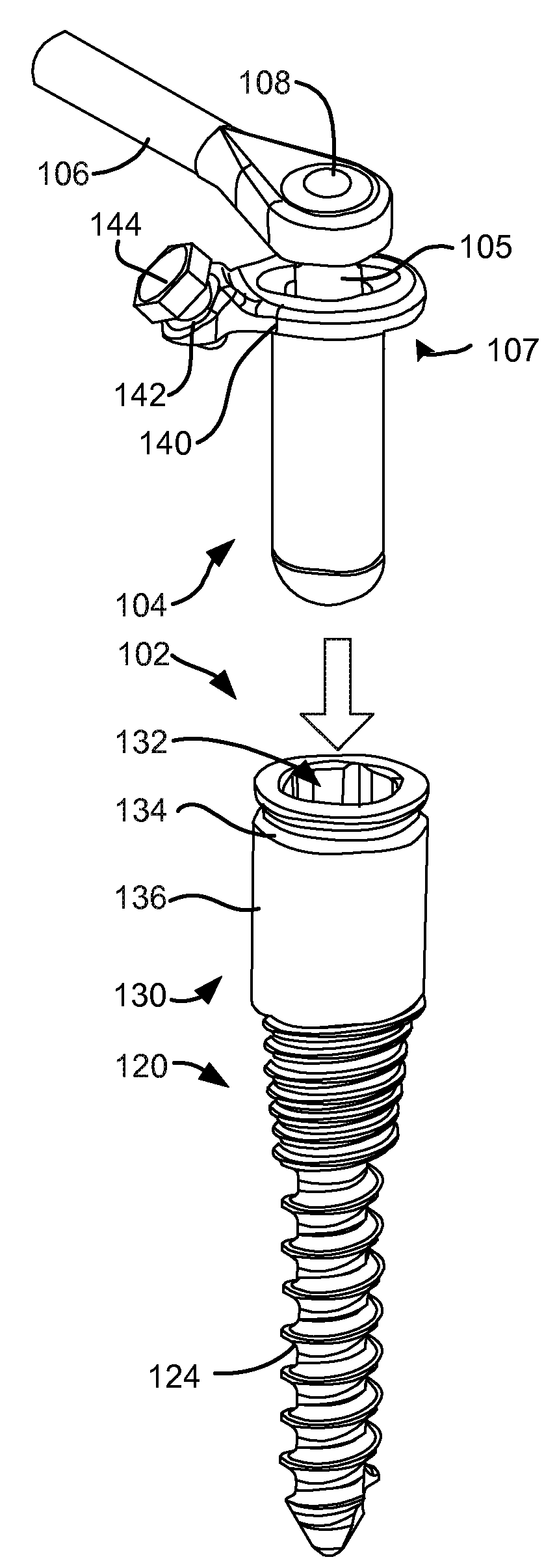
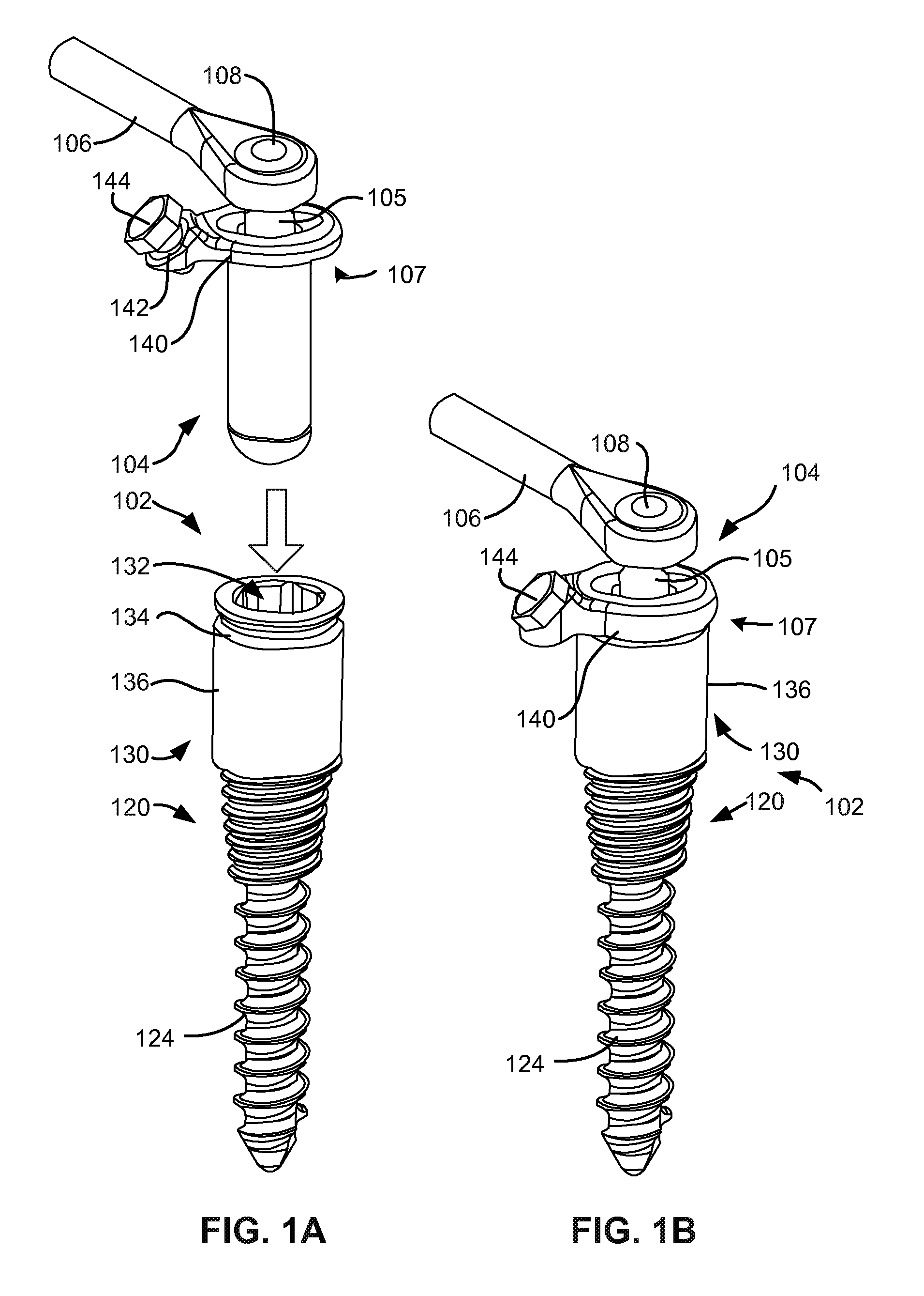
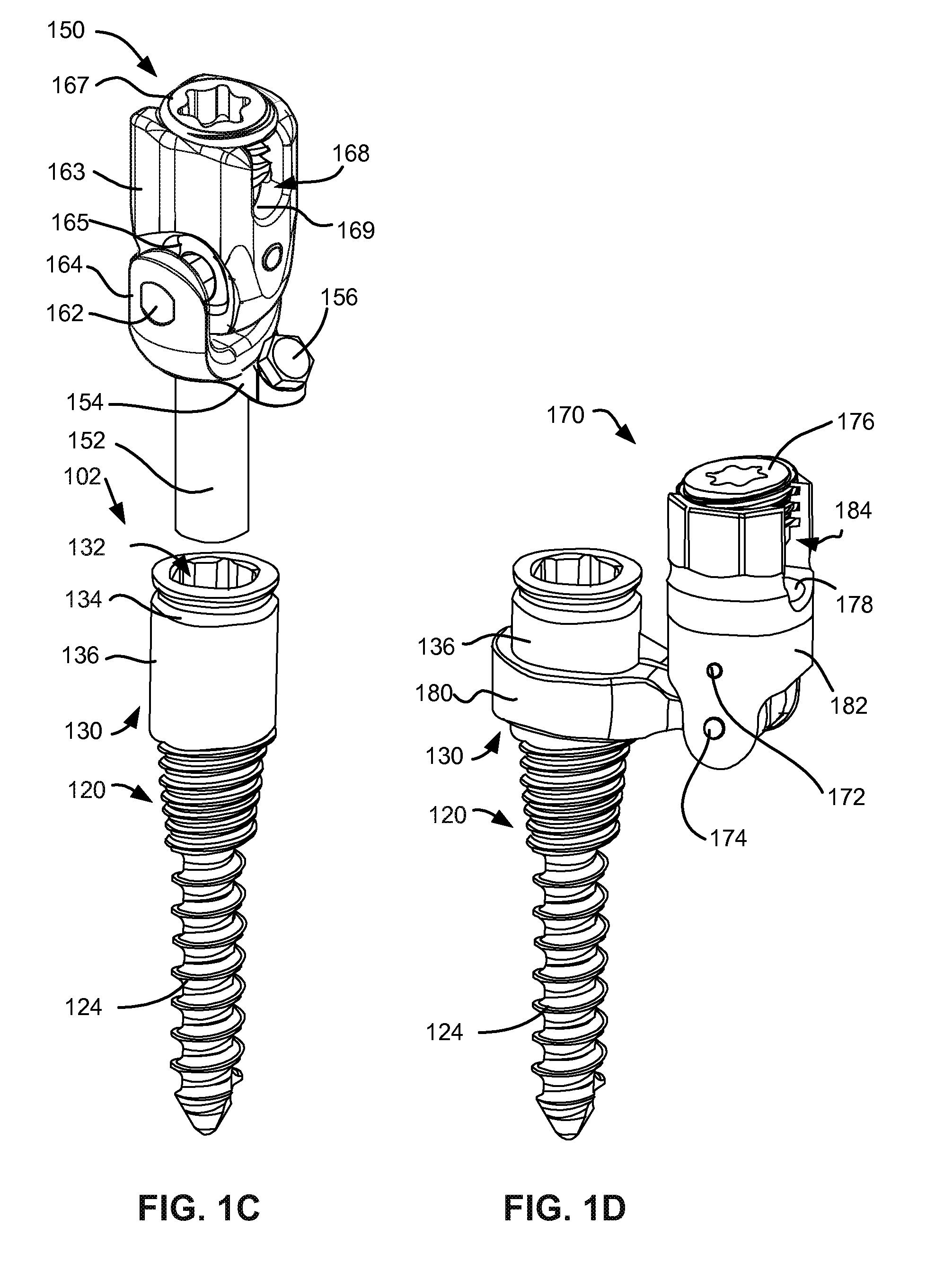
A cannulated bone anchor comprising a self-centering ball-joint suitable for use in a spine stabilization prosthesis which supports the spine while providing for the preservation of spinal motion. The cannulated bone anchor has a deflectable post partially received in a socket of a housing formed in the head of the bone anchor. A centering rod received partially in the post and partially within the housing operates to align the post with the longitudinal axis of the bone anchor. Deflection of the post bends the centering rod which in turn applies a restoring force upon the post. The centering rod includes an inner-superelastic core and an outer polymer sheath.

Description

CLAIM TO PRIORITY[0001]This patent application claims priority to the following patents and patent applications:[0002]The present application is a continuation-in-part of U.S. patent application Ser. No. 13 / 206,286, filed Aug. 9, 2011, entitled “Low Profile Spinal Prosthesis Incorporating a Cannulated Bone Anchor Having a Deflectable Post and a Compound Spinal Rod” and which is a continuation-in-part of U.S. patent application Ser. No. 13 / 098,280, filed Apr. 29, 2011, entitled “Low Profile Spinal Prosthesis Incorporating A Bone Anchor Having A Deflectable Post And A Compound Spinal Rod” and which is a continuation-in-part of U.S. patent application Ser. No. 12 / 959,200, filed Dec. 2, 2010, entitled “Low Profile Spinal Prosthesis Incorporating A Bone Anchor Having A Deflectable Post And A Compound Spinal Rod”. All of these applications are incorporated by reference in their entirety.CROSS-REFERENCES TO RELATED APPLICATIONS[0003]This application is related to all of the following appli...

Claims


Application Information

Patent Timeline
Patent Type & Authority Applications(United States)
IPC IPC(8): A61B17/70A61B17/86
CPCA61B17/7005A61B17/7007A61B17/7011A61B17/7023A61B17/7025A61B17/7026A61B17/7046A61B17/7031A61B17/7043A61B17/7049A61B17/7082A61B17/7091A61B2019/307A61B17/7028A61B2090/037
Inventor WINSLOW, CHARLES J.MITCHELL, STEVEN T.FLYNN, JOHN J.ZUCHERMAN, JAMES F.HSU, KEN Y.KLYCE, HENRY A.KLYCE, H. ADAM R.
Owner SPARTEK MEDICAL
Learn More