
Corneal inlay with nutrient transport structures

a technology of nutrient transport and inlay, which is applied in the field of corneal implants, can solve the problems of uncompensated cylindrical refractive error, corneal astigmatism, and individuals' inability to see up close without vision correction, and achieve the effect of improving patient vision and enhancing nutrient flow

Active Publication Date: 2012-06-07
CORNEAGEN INC
View PDF4 Cites 63 Cited by
  • Summary
  • Abstract
  • Description
  • Claims
  • Application Information

AI Technical Summary

Benefits of technology

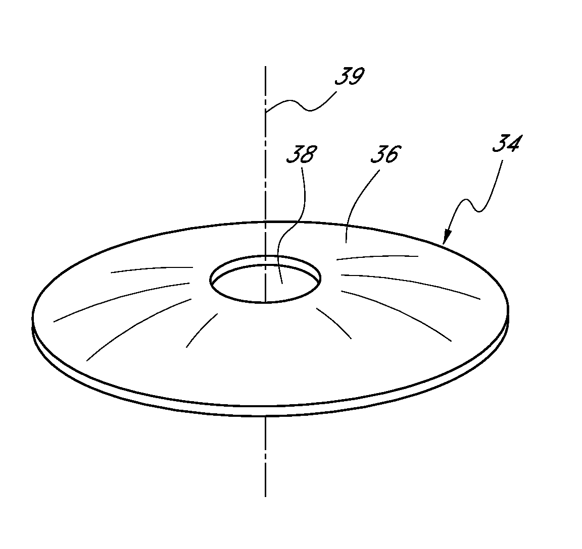
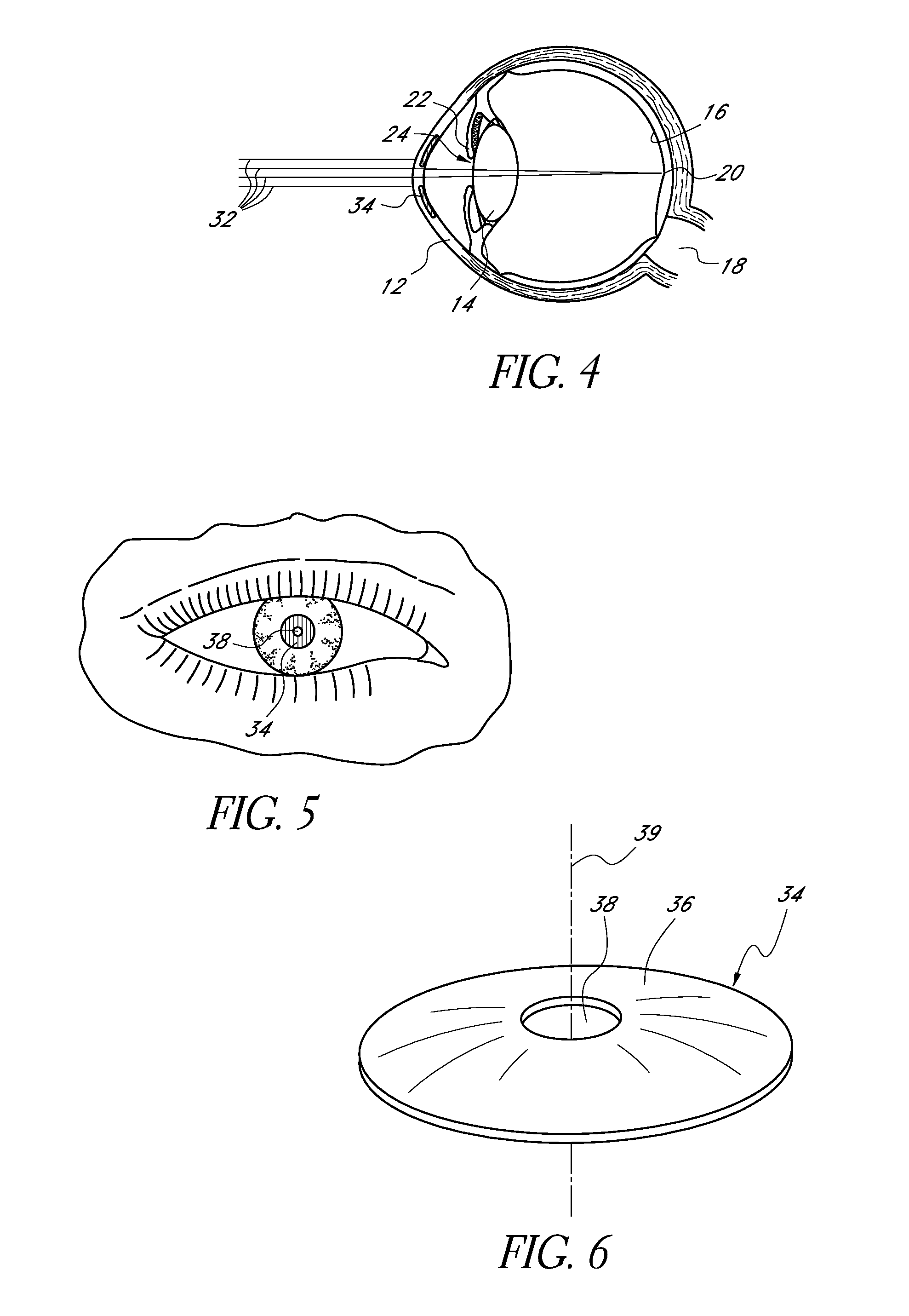
[0009]An aperture corneal inlay can have many forms, such as including a light blocking (e.g., opaque) annulus surrounding an aperture. Such a device is sometimes referred to herein as a “mask.” In some embodiments, the small aperture can be a pin-hole aperture. Long-term acceptance of such inlays by patients can be enhanced by facilitating transmission of nutrients between tissues located anteriorly and posteriorly of the inlay. For example, the inlay can be made porous such that certain nutrients can readily pass therethrough. If the inlay is very thin, small perforations or holes can be formed through the annulus for this purpose.
[0012]In a further embodiment, a method for improving the vision of a patient is provided. The method can include providing a mask that includes an anterior surface configured to reside adjacent a first corneal layer, a posterior surface configured to reside adjacent a second corneal layer, and an aperture configured to transmit light along an optic axis. The mask can further include a substantially opaque portion extending at least partially between the aperture and an outer periphery of the mask, and the opaque portion can include an inner region, an outer region, and a central region disposed between the inner and outer regions. A plurality of holes can extend between the anterior surface and the posterior surface, and the holes can be positioned at locations in the inner, outer and central regions. The central region can include a first porosity, the inner region can include a second porosity, the outer region can include a third porosity, and the first porosity can be greater than the second porosity or the third porosity. The method can further include inserting the mask into a cornea.
[0013]In certain embodiments, a corneal inlay is provided. The corneal inlay can include an anterior surface configured to reside adjacent a first corneal layer, a posterior surface configured to reside adjacent a second corneal layer, and an opening configured to transmit light therethrough. The corneal inlay can further include an outer zone adapted to substantially prevent transmission of light therethrough. The outer zone can have nutrient transport structures disposed therein, and the outer zone can be configured to provide enhanced nutrient flow at locations spaced away from the outer periphery compared to locations adjacent to the outer periphery.

Problems solved by technology

The cornea also may be asymmetric or toric, resulting in an uncompensated cylindrical refractive error referred to as corneal astigmatism.
In most individuals, the ability to accommodate diminishes with age and these individuals cannot see up close without vision correction.

Method used


Image

  • Corneal inlay with nutrient transport structures
  • Corneal inlay with nutrient transport structures
  • Corneal inlay with nutrient transport structures

Examples


Embodiment Construction

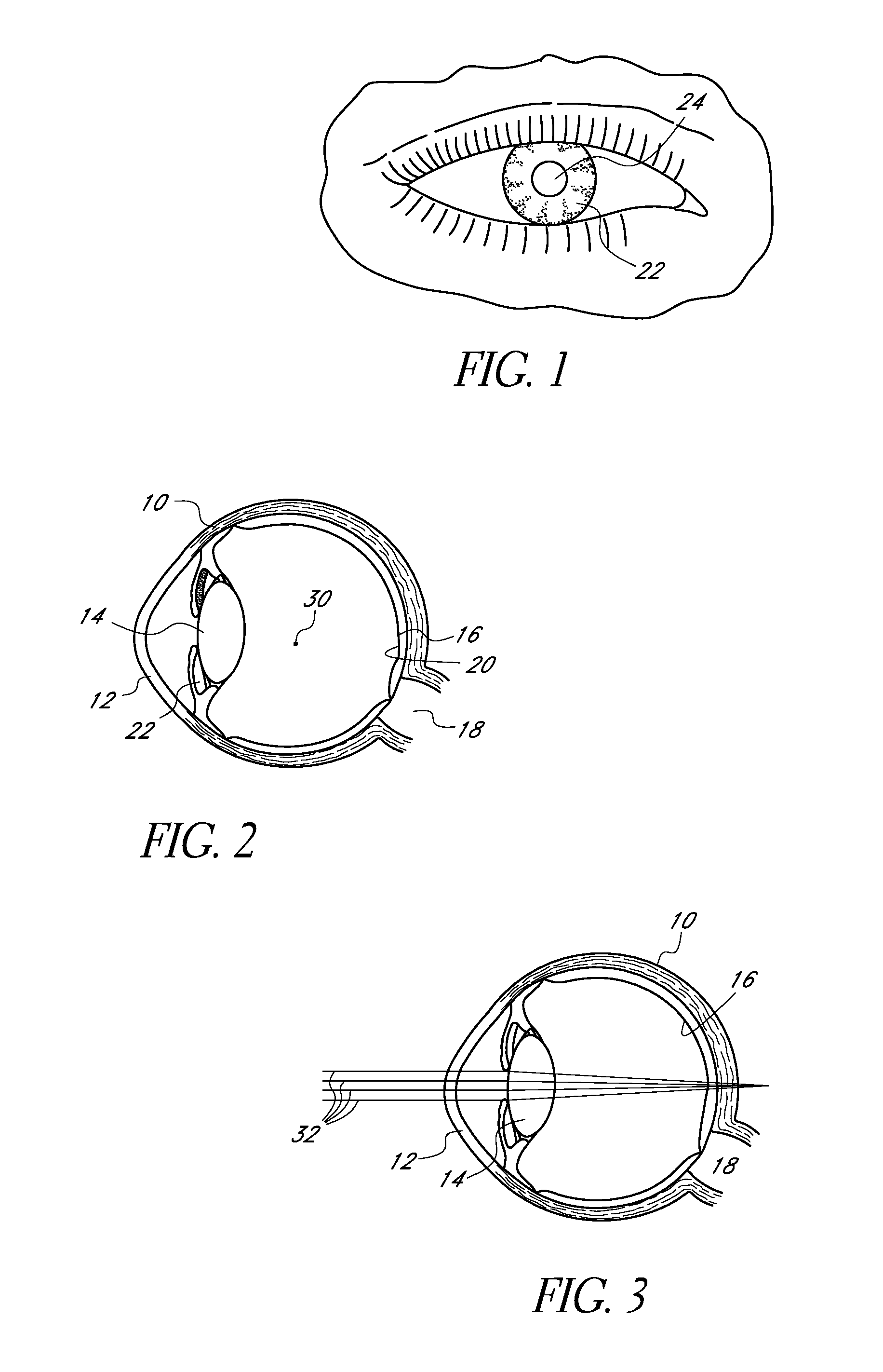
[0081]This application is directed to corneal inlays (e.g., masks) for improving the depth of focus of an eye of a patient and methods and apparatuses for making such corneal inlays. The masks generally employ pin-hole vision correction and have nutrient transport structures in some embodiments. The masks may be applied to the eye in any manner and in any location, e.g., as an implant in the cornea (sometimes referred to as a “corneal inlay”). The masks can also be embodied in or combined with lenses and applied in other regions of the eye, e.g., as or in combination with contact lenses or intraocular lenses. In some applications, discussed further below, the masks are formed of a stable material, e.g., one that can be implanted permanently. Corneal inlays with an opening may also be used to treat aniridia.

I. Overview of Depth of Focus Vision Correction

[0082]As discussed above, mask that has a pinhole aperture may be used to improve the depth of focus of a human eye. As discussed ab...


PUM


Abstract

Corneal inlays and masks and methods of improving vision of a patient with corneal inlays and masks are provided. Masks with an aperture can improve the vision of a patient, such as by increasing the depth of focus of an eye of a patient. For example, a mask can have an annular portion with a relatively low visible light transmission surrounding a relatively high transmission central portion, such as a clear lens or aperture. This provides an annular mask with a small aperture for light to pass through to the retina to increase depth of focus. The mask may also include nutrient transport structures that provide nutrient flow through mask to prevent nutrient depletion. These nutrient transport structures can be configured to concentrate nutrient transmission near a center region of the mask to provide more nutrient flow near the center region.

Description

CROSS-REFERENCE TO RELATED APPLICATIONS[0001]This application claims the benefit of U.S. Provisional Application No. 61 / 233,802, filed Aug. 13, 2009, the entirety of which is hereby incorporated by reference.BACKGROUND[0002]1. Field[0003]This application relates generally to the field of corneal implants. For example, this application is directed to corneal inlays with an aperture to improve depth of focus (e.g. “masked” corneal inlays) and methods of making.[0004]2. Description of the Related Art[0005]The human eye functions to provide vision by transmitting and focusing light through a clear outer portion called the cornea, and further refining the focus of the image by way of a crystalline lens onto a retina. The quality of the focused image depends on many factors including the size and shape of the eye, and the transparency of the cornea and the lens.[0006]The optical power of the eye is determined by the optical power of the cornea and the crystalline lens. In a normal, health...

Claims


Application Information

Patent Timeline
IPC IPC(8): A61F2/14
CPCA61F2/145A61F2/142A61F2/1451A61F2250/0024A61F2/15A61F2/14A61F2/02G02C7/165G02C7/046
Inventor CHRISTIE, BRUCEPETERSON, EDWARD W.VAN DE POL, CORINA
Owner CORNEAGEN INC
Learn More