Fluidic deflagration-to-detonation initiation obstacles

a technology of initiation obstacles and fluid flow, which is applied in the direction of machines/engines, gas turbine plants, intermittent jet plants, etc., can solve the problems of creating pressure drop within the chamber, and achieve the effect of enhancing the turbulence of the fluid flow and flame acceleration

Active Publication Date: 2012-06-14
GENERAL ELECTRIC CO
View PDF8 Cites 17 Cited by
  • Summary
  • Abstract
  • Description
  • Claims
  • Application Information

AI Technical Summary

Benefits of technology

[0005]Briefly, in accordance with one embodiment, a detonation chamber for a pulse detonation combustor is provided. The detonation chamber includes a plurality of aerodynamic jets disposed adjacent an exterior of a sidewall of the detonation chamber and a plurality of openings formed in the sidewall of the detonation chamber. Each of the plurality of openings is in fluidic communication with one of the plurality of aerodynamic jets. The plurality of aerodynamic jets are adapted to create a plurality of jet flows of a fluid within the detonation chamber during a combustion cycle defining a plurality of initiation obstacles within the detonation chamber to enhance a turbulence of a fluid flow and flame acceleration through the detonation chamber.
[0006]In accordance with another embodiment, a detonation chamber for a pulse detonation combustor is provided. The detonation chamber includes a plurality of aerodynamic jets disposed adjacent an exterior of a sidewall of the detonation chamber; an inlet and an outlet, wherein the plurality of aerodynamic jets are disposed between the inlet and the outlet; and a plurality of openings formed in the sidewall of the detonation chamber, wherein each of the plurality of openings is in fluidic communication with one of the plurality of aerodynamic jets. The plurality of aerodynamic jets are adapted to create a plurality of jet flows of a fluid within the detonation chamber during a combustion cycle defining a plurality of initiation obstacles within the detonation chamber to enhance a turbulence of a fluid flow and flame acceleration through the detonation chamber.
[0007]In accordance with another embodiment, a pulse detonation combustor is provided. The pulse detonation combustor includes at least one detonation chamber; an oxidizer supply section for feeding an oxidizer into the detonation chamber; a fuel supply section for feeding a fuel into the detonation chamber; and an igniter for igniting a mixture of the gas and the fuel in the detonation chamber. The detonation chamber further comprises a plurality of aerodynamic jets disposed adjacent an exterior of a sidewall of the detonation chamber and a plurality of openings formed in the sidewall of the detonation chamber, wherein each of the plurality of openings is in fluidic communication with one of the plurality of aerodynamic jets. The plurality of aerodynamic jets are adapted to create a plurality of jet flows of a fluid within the detonation chamber during a combustion cycle defining a plurality of initiation obstacles within the detonation chamber to enhance a turbulence of a fluid flow and flame acceleration through the detonation chamber.

Problems solved by technology

The problem with obstacles for cyclic detonation devices is that they create a pressure drop within the chamber during the fill process.

Method used


Image

  • Fluidic deflagration-to-detonation initiation obstacles
  • Fluidic deflagration-to-detonation initiation obstacles
  • Fluidic deflagration-to-detonation initiation obstacles

Examples


Embodiment Construction

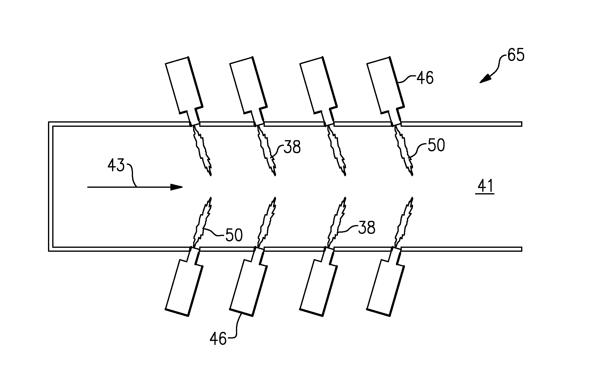
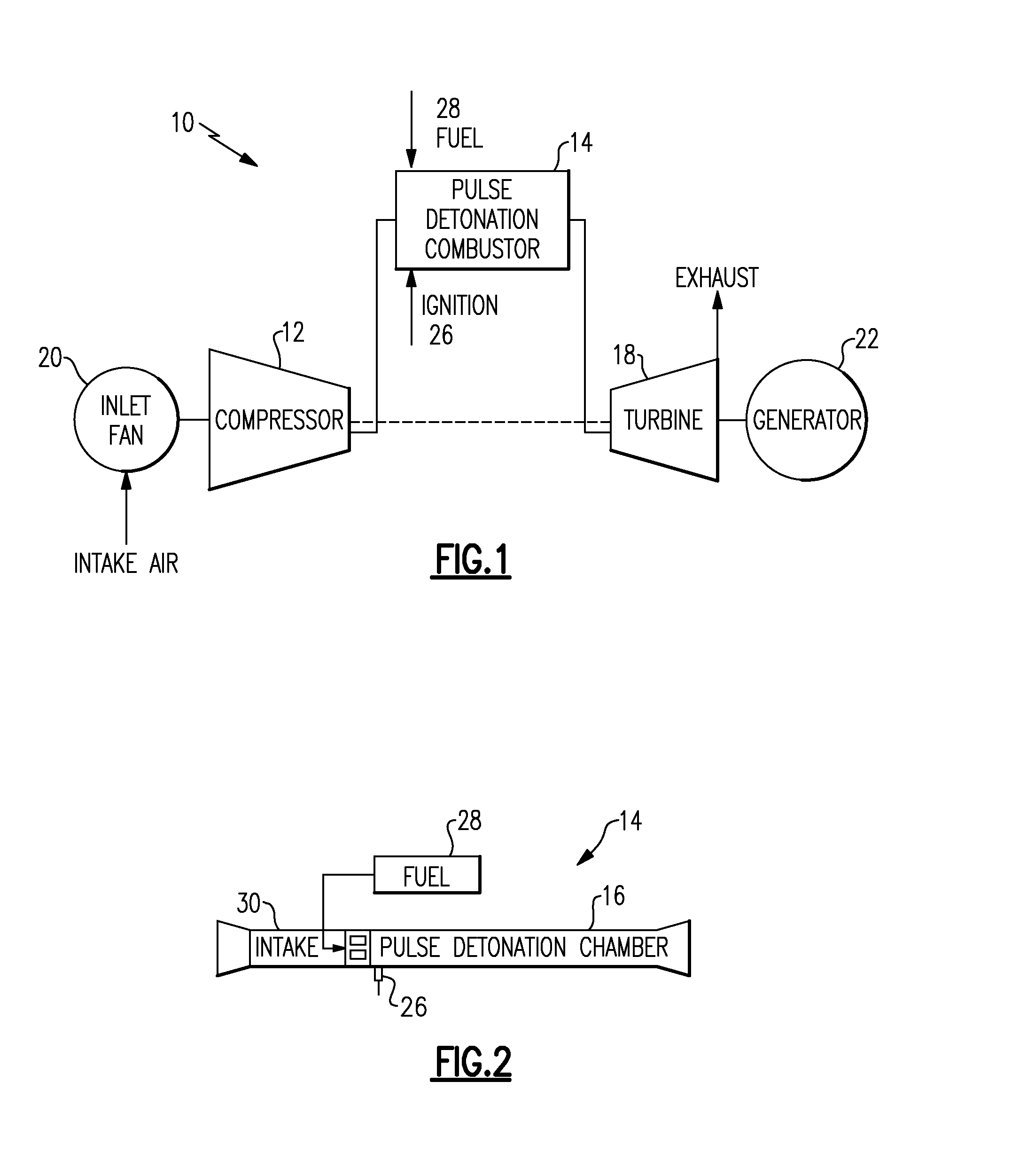
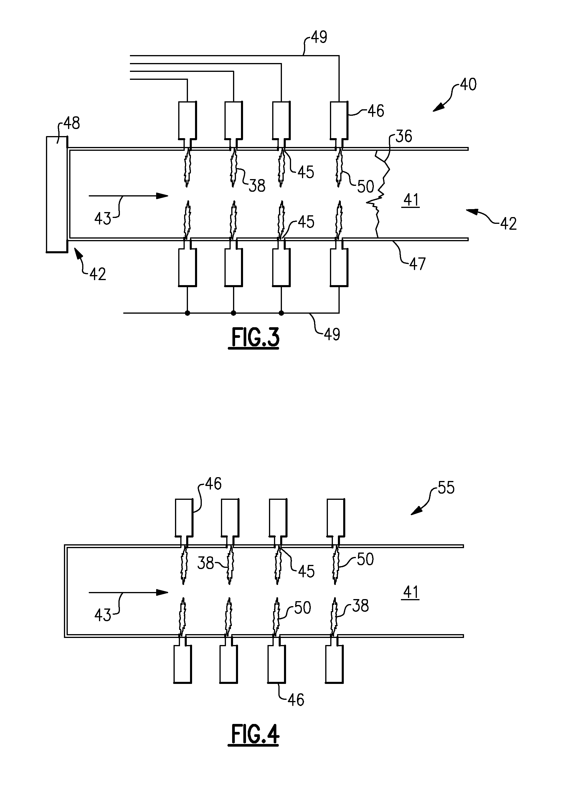
[0020]Referring now to the drawings, one or more specific embodiments of the present disclosure will be described below. In an effort to provide a concise description of these embodiments, not all features of an actual implementation are described in the specification. Illustrated in FIGS. 1 and 2, are various pulse detonation engine systems 10 that convert kinetic and thermal energy of the exhausting combustion products into motive power necessary for propulsion and / or generating electric power. Illustrated in FIG. 1 is an exemplary embodiment of a pulse detonation combustor 14 in a pulse detonation turbine engine concept 10. Illustrated in FIG. 2 is an exemplary embodiment of a pulse detonation combustor 14 in a pure supersonic propulsion vehicle. The pulse detonation combustor 14, shown in FIG. 1 or FIG. 2, includes a detonation chamber 16 having an oxidizer supply section (e.g., an air intake) 30 for feeding an oxidizer (e.g., oxidant such as air) into the detonation chamber 16,...


PUM


Abstract

A detonation chamber and a pulse detonation combustor including a detonation chamber, wherein the detonation chamber includes a plurality of aerodynamic jets disposed adjacent an exterior of a sidewall of the detonation chamber. The detonation chamber further includes a plurality of openings formed in the sidewall of the detonation chamber, wherein each of the plurality of openings is in fluidic communication with one of the plurality of aerodynamic jets. The plurality of aerodynamic jets are adapted to create a plurality of jet flows of a fluid within the detonation chamber during a combustion cycle defining a plurality of initiation obstacles within the detonation chamber to enhance a turbulence of a fluid flow and flame acceleration through the detonation chamber.

Description

BACKGROUND[0001]The present disclosure generally relates to cyclic pulsed detonation combustors (PDCs) and more particularly, enhancing the deflagration-to-detonation transition (DDT) process by integrating fluidic initiation obstacles.[0002]In a generalized pulse detonation combustor, fuel and oxidizer (e.g., oxygen-containing gas such as air) are admitted to an elongated detonation chamber at an upstream inlet end. An igniter is used to initiate this combustion process. Following a successful transition to detonation, a detonation wave propagates toward the outlet at supersonic speed causing substantial combustion of the fuel / air mixture before the mixture can be substantially driven from the outlet. The result of the combustion is to rapidly elevate pressure within the combustor before substantial gas can escape through the combustor exit. The effect of this inertial confinement is to produce near constant volume combustion. Such devices can be used to produce pure thrust or can ...

Claims


Application Information

Patent Timeline
Patent Type & Authority Applications(United States)
IPC IPC(8): F02K7/02
CPCF02C5/11F02K7/02
Inventor BRUMBERG, JUSTIN THOMASRASHEED, ADAM
Owner GENERAL ELECTRIC CO
Why Eureka
Try Eureka