
Solar thermal energy collector

Active Publication Date: 2012-06-14
WEEKLEY JOHN C
View PDF6 Cites 13 Cited by
  • Summary
  • Abstract
  • Description
  • Claims
  • Application Information

AI Technical Summary

Benefits of technology

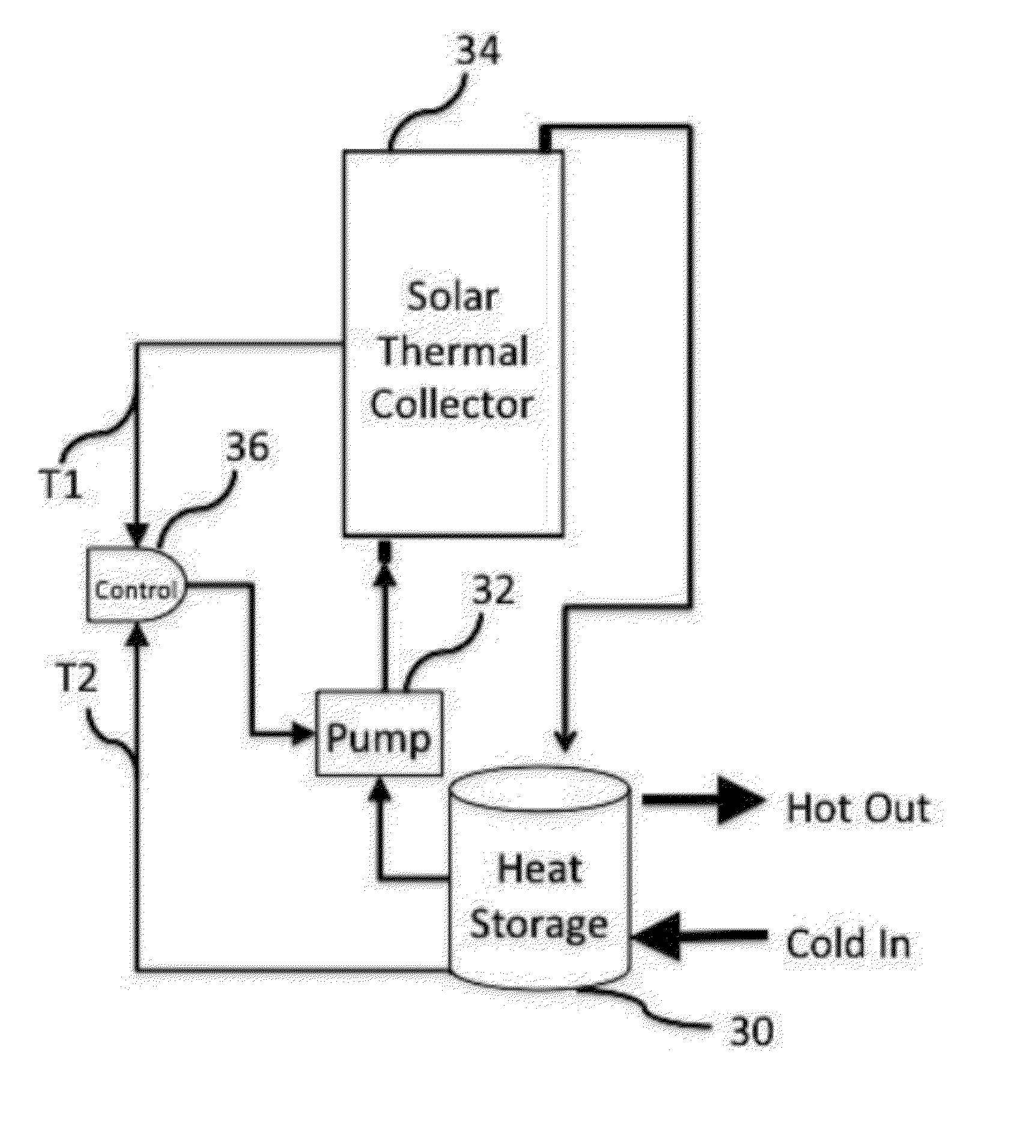
[0008]The present invention reduces the first cost and improves the economic payback in four ways. 1) The design and construction of the invention uses lower cost materials, fewer materials, and less labor than any current solar energy collector, relative to the value of the energy collected. 2) The collector is designed for installation in new construction as an integral component of the structure, thus eliminating the cost of the construction materials and labor that would have otherwise been used. 3) The design and construction permit installation using less labor and installation materials than other solar thermal collectors. 4) The design allows the installation of solar photovoltaic panels on the top of the solar thermal collector, with the benefit of significantly improving the efficiency of the solar photovoltaic collector.
[0009]In accordance with one embodiment a collector module is constructed as a metal plate sandwich. on which the top plate has a selective surface that absorbs solar irradiance, and a bottom plate that is formed to contain and direct the flow of heat transfer fluid. The metal plates can be fabricated from galvanized steel, stainless steel or aluminum, for example. The resultant conduits and manifolds are an integral part of the joined top and bottom plate, thereby eliminating the need for separate pipes, tubes, or the like.
[0012]Another feature of an embodiment of the invention is that it is adapted to the mounting of solar photovoltaic collectors above the top plate of the collector modules, potentially improving the performance of both the thermal collector and the photovoltaic collector.

Problems solved by technology

Moreover, such heat-exchanger is not adapted either for installation in the joists or studs of a building structure or for the addition of photovoltaic solar electricity generation.
All known solar thermal energy collectors suffer from relatively high cost due to a combination of high material costs and / or high manufacturing cost.
Thus, the largest barrier to solar heating system adoption is the high first cost and the resulting poor economic payback.

Method used


Image

  • Solar thermal energy collector
  • Solar thermal energy collector
  • Solar thermal energy collector

Examples


Embodiment Construction

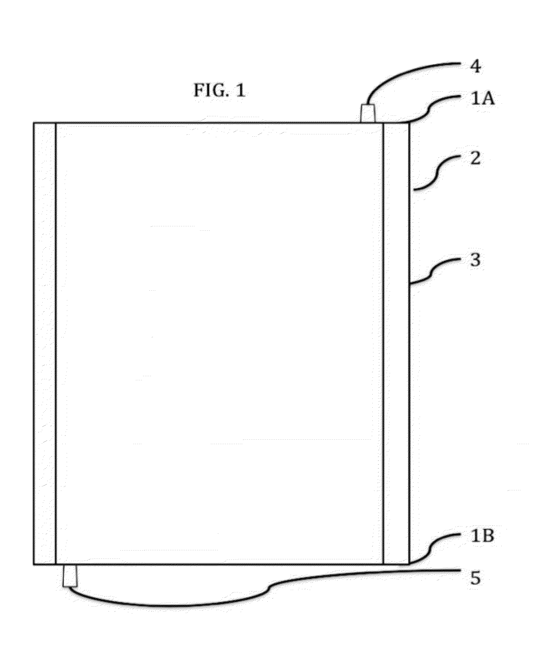
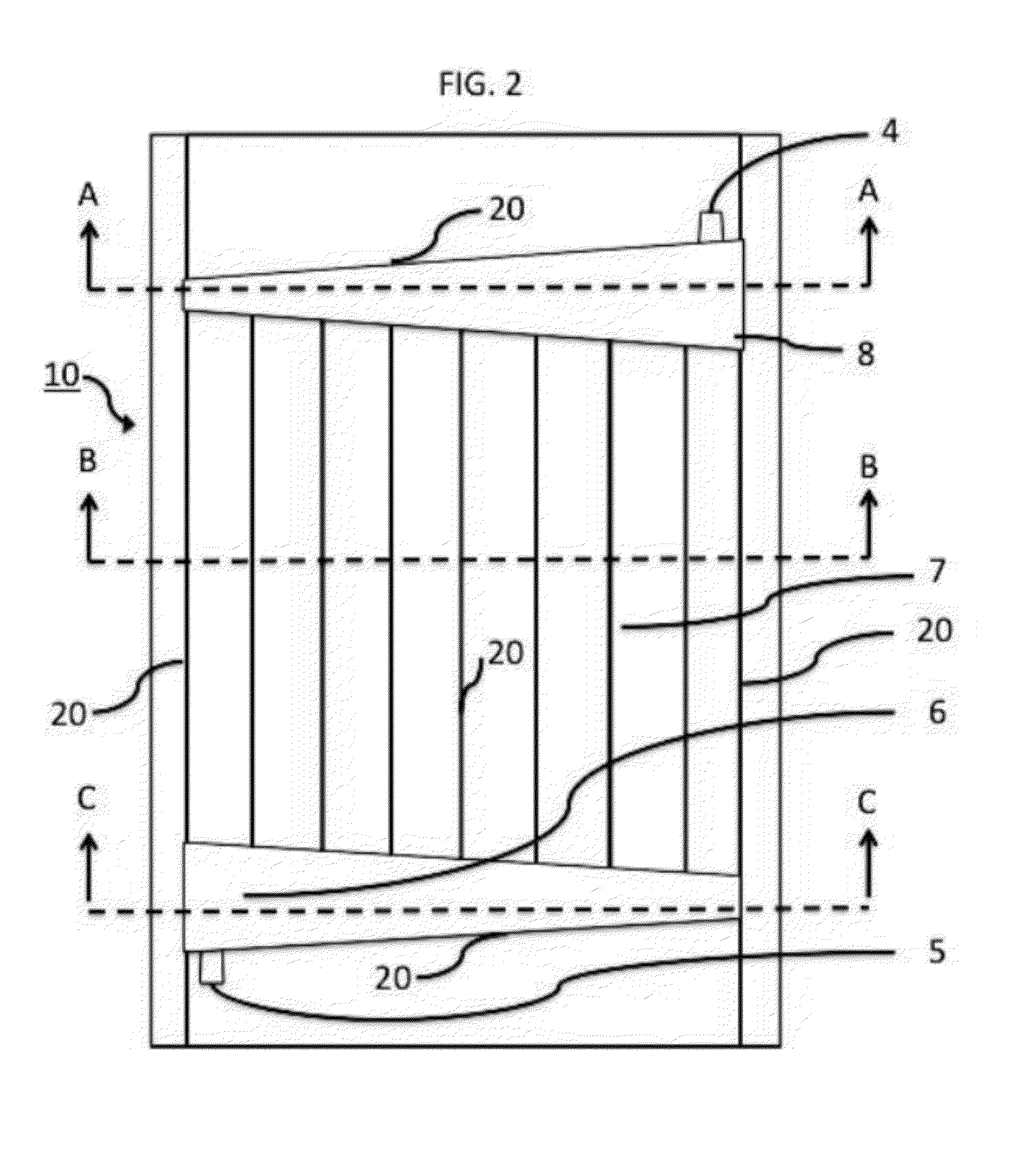
[0024]Refer now to FIG. 1, which is a front elevation view schematically illustrating the solar thermal collector module. The surface of the first metallic plate of the multi-layer sandwich structure thermal collector module 3 can be coated with black paint, or preferably, a selective surface that increases the solar thermal absorption, while minimizing the energy losses to emission and convection. The top 1A and the bottom 1B edges are formed to permit the module to be easily installed in an array and column pattern on the roof or wall of a building structure, and provide for a weather flashing and seal. The sides 2 of the solar thermal collector may either be formed to be interlocking, or may be formed to facilitate the mechanical attachment of photovoltaic solar collectors above the solar thermal energy collector. The heat transfer fluid connections 4 and 5 would normally not be visible in this view and are shown merely to provide a schematic illustration in FIG. 1. Refer now to ...


PUM


Abstract

A solar thermal energy collection module formed by a sandwich of metal plates. The metal plates collect solar radiant energy and convert that to thermal energy in a heat transfer fluid that flows through conduits and manifolds formed between the plates. The collector module may be directly integrated into the exterior of building structures in an array. The collector module also may be glazed or integrated with photovoltaic solar panels.

Description

CROSS-REFERENCE TO RELATED APPLICATION[0001]This application claims benefit of priority under 35 U.S.C. 119(e) to U.S. Provisional Application No. 61 / 422,888 entitled “SOLAR THERMAL ENERGY COLLECTOR” and filed on Dec. 14, 2010, the entire contents of which are incorporated by reference.BACKGROUND OF THE INVENTION[0002]1. Field of the Invention[0003]This invention relates to solar thermal energy collectors. Solar thermal energy collectors absorb solar irradiance and convert the light wave energy to heat energy. The heat energy is transferred to a fluid and then stored and used for heating residential and commercial applications. Some typical uses are heating swimming pools, heating domestic hot water, and heating buildings.[0004]2. Discussion of the Related Art[0005]Solar heating systems for generating hot water for commercial buildings, homes and swimming pools are well known and commercially available. A significant portion of a solar heating system is the solar thermal energy coll...

Claims


Application Information

Patent Timeline
IPC IPC(8): H01L31/058E04D13/18F24J2/48F28F3/12F24J2/22F24S10/55
CPCF24J2/204Y02B10/12Y02B10/20H02S40/44Y02E10/44Y02E10/60Y02B10/70F24S10/503Y02B10/10Y02E10/50
Inventor WEEKLEY, JOHN C.
Owner WEEKLEY JOHN C
Learn More