Capacitive electromechanical transducer apparatus and method for adjusting its sensitivity

Inactive Publication Date: 2012-06-14
CANON KK
View PDF11 Cites 12 Cited by
  • Summary
  • Abstract
  • Description
  • Claims
  • Application Information

AI Technical Summary

Benefits of technology

[0008]In the present invention, at least either addition of a material or removal of a material is performed onto or from at least one of the cells, and thus the reception sensitivities of the cells or those of the elements with respect to an elastic wave such as an ultrasonic wave can be adjusted (that is, an output signal generated upon reception of, for example, an ultrasonic wave can be adjusted), or the variations in reception sensitivity among the elements can be reduc

Problems solved by technology

When a capacitive electromechanical transducer apparatus in which a plurality of elements are arranged, each element including a plurality of cells electrically connected to each other, is used to detect an elastic wave

Method used


Image

  • Capacitive electromechanical transducer apparatus and method for adjusting its sensitivity
  • Capacitive electromechanical transducer apparatus and method for adjusting its sensitivity
  • Capacitive electromechanical transducer apparatus and method for adjusting its sensitivity

Examples


Example

First Embodiment

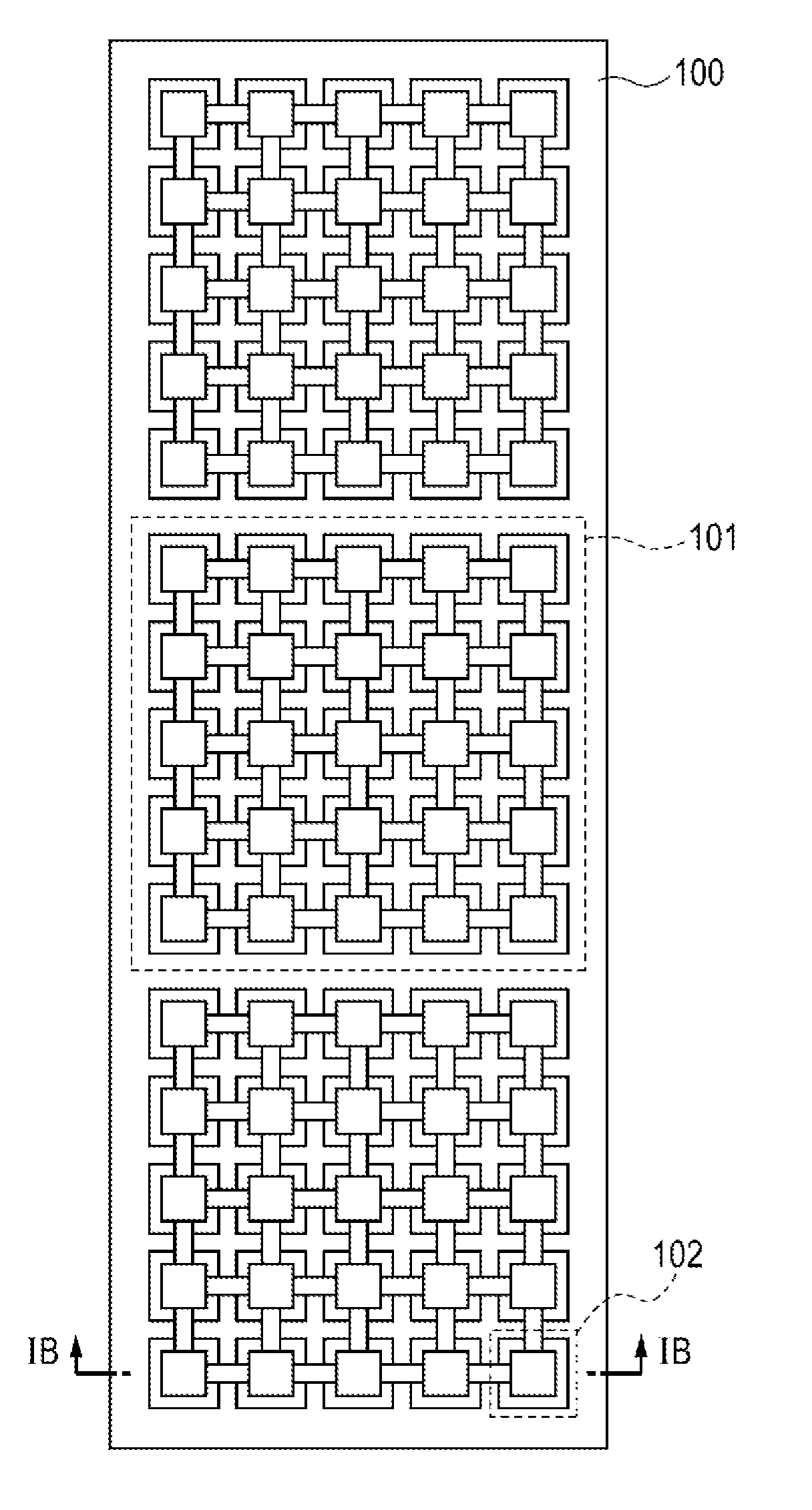
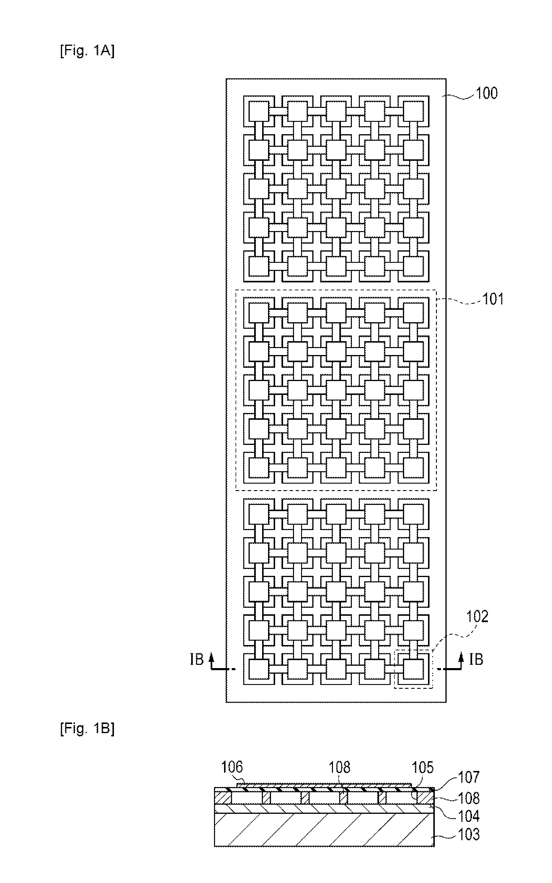
[0024]In the following, a capacitive electromechanical transducer apparatus according to a first embodiment of the present invention before sensitivity adjustment processing (the capacitive electromechanical transducer apparatus having been manufactured as originally planned) will be described with reference to the drawings. As shown in FIGS. 1A and 1B, a capacitive electromechanical transducer apparatus 100 includes a plurality of elements 101. In each of the elements 101, a plurality of cells 102 are electrically connected in parallel with each other. In FIG. 1A, 25 cells 102 are arranged in the element 101, which is a component; however, the number of the cells 102 is not limited thereto as long as there are one or more cells in the element 101. Moreover, the capacitive electromechanical transducer apparatus 100 includes three elements 101 arranged in one dimension; however, the elements 101 may be arranged in two dimensions. In the first embodiment, the cells 102...

Example

Second Embodiment

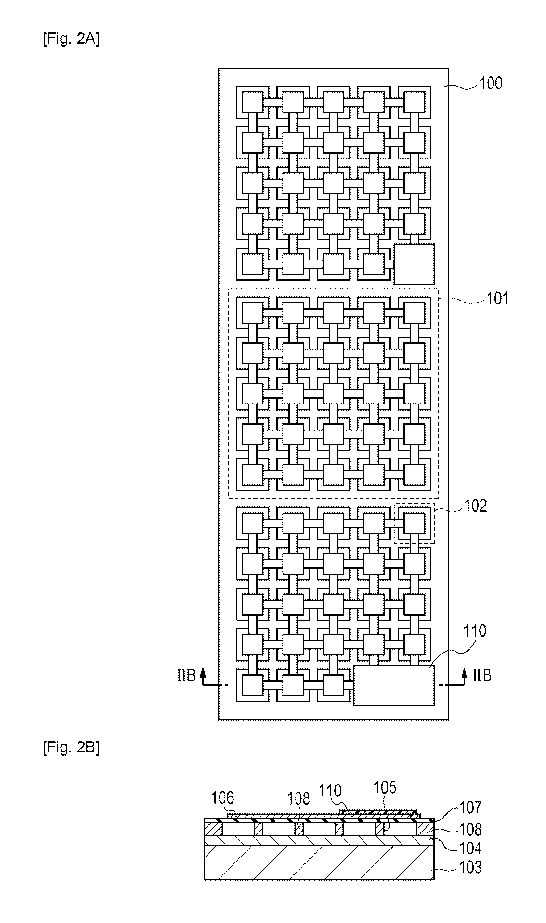
[0031]A capacitive electromechanical transducer apparatus according to a second embodiment will be described. The basic structure of the capacitive electromechanical transducer apparatus according to the second embodiment is similar to that shown in the first embodiment. In the second embodiment, the vibrating membrane and upper electrodes of some of the cells are removed within the elements in accordance with the reception sensitivity of each of the elements measured in advance. As a result, an intensity of an output signal sent from the cells upon reception of an ultrasonic wave or the like can be reduced and the reception sensitivities of a plurality of elements can be made almost equal to each other. FIG. 4A shows a top view of a capacitive electromechanical transducer apparatus 100 whose reception sensitivity has been adjusted by a sensitivity adjustment processing method according to the second embodiment. FIG. 4B shows a sectional view taken along line IVB-IV...

Example

Third Embodiment

[0033]A capacitive electromechanical transducer apparatus according to a third embodiment will be described. The basic structure of the capacitive electromechanical transducer apparatus according to the third embodiment is also similar to that shown in the first embodiment. In the third embodiment, electrical connection between the upper electrodes of some cells within each element is cut in accordance with the reception sensitivity of the element measured in advance. As a result, an intensity of an output signal sent from the cells upon reception of a sound wave or the like can be reduced and the reception sensitivities of a plurality of elements with respect to a sound wave or the like can be made almost equal to each other. FIG. 5A shows a top view of a capacitive electromechanical transducer apparatus 100 whose reception sensitivity has been adjusted by a sensitivity adjustment processing method according to the third embodiment. FIG. 5B shows a sectional view ta...


PUM

PropertyMeasurementUnit
Sensitivityaaaaaaaaaa

Abstract

A technology that makes it possible to adjust, through processing, an output signal sent from a capacitive electromechanical transducer apparatus such as a CMUT upon reception of an elastic wave is provided.
A capacitive electromechanical transducer apparatus 100 includes cells 102 that include a first electrode 104 and second electrodes 106, each of which is disposed so as to be opposite the first electrode 104 with a cavity 105 therebetween. In the capacitive electromechanical transducer apparatus 100, at least one of the cells 102 includes a processed unit on which at least either addition of a material or removal of a material is performed as processing.

Description

TECHNICAL FIELD[0001]The present invention relates to a capacitive electromechanical transducer apparatus such as a capacitive ultrasonic transducer apparatus, and a method for adjusting the sensitivity of the capacitive electromechanical transducer apparatus.BACKGROUND ART[0002]Recently, capacitive electromechanical transducer apparatuses manufactured by performing a micromachining process have been studied actively. General capacitive electromechanical transducer apparatuses include cells that include a lower electrode, a vibrating membrane that is supported and arranged with a predetermined space from the lower electrode, and upper electrodes arranged on a surface of the vibrating membrane. These capacitive electromechanical transducer apparatuses are used as, for example, capacitive micromachined ultrasonic transducers (CMUTs).[0003]A CMUT performs at least either conversion of an electric signal into an ultrasonic wave or conversion of an ultrasonic wave into an electric signal...

Claims


Application Information

Patent Timeline
IPC IPC(8): H02N1/08H02K15/00
CPCY10T29/49009B06B1/0292
Inventor FUJII, KAZUNARIAKIYAMA, TAKAHIROKATO, AYAKO
Owner CANON KK
Why Eureka
Try Eureka