Magnetic resonance imaging apparatus and magnetic resonance imaging method
- Summary
- Abstract
- Description
- Claims
- Application Information
AI Technical Summary
Benefits of technology
Problems solved by technology
Method used
Image

Examples
first embodiment
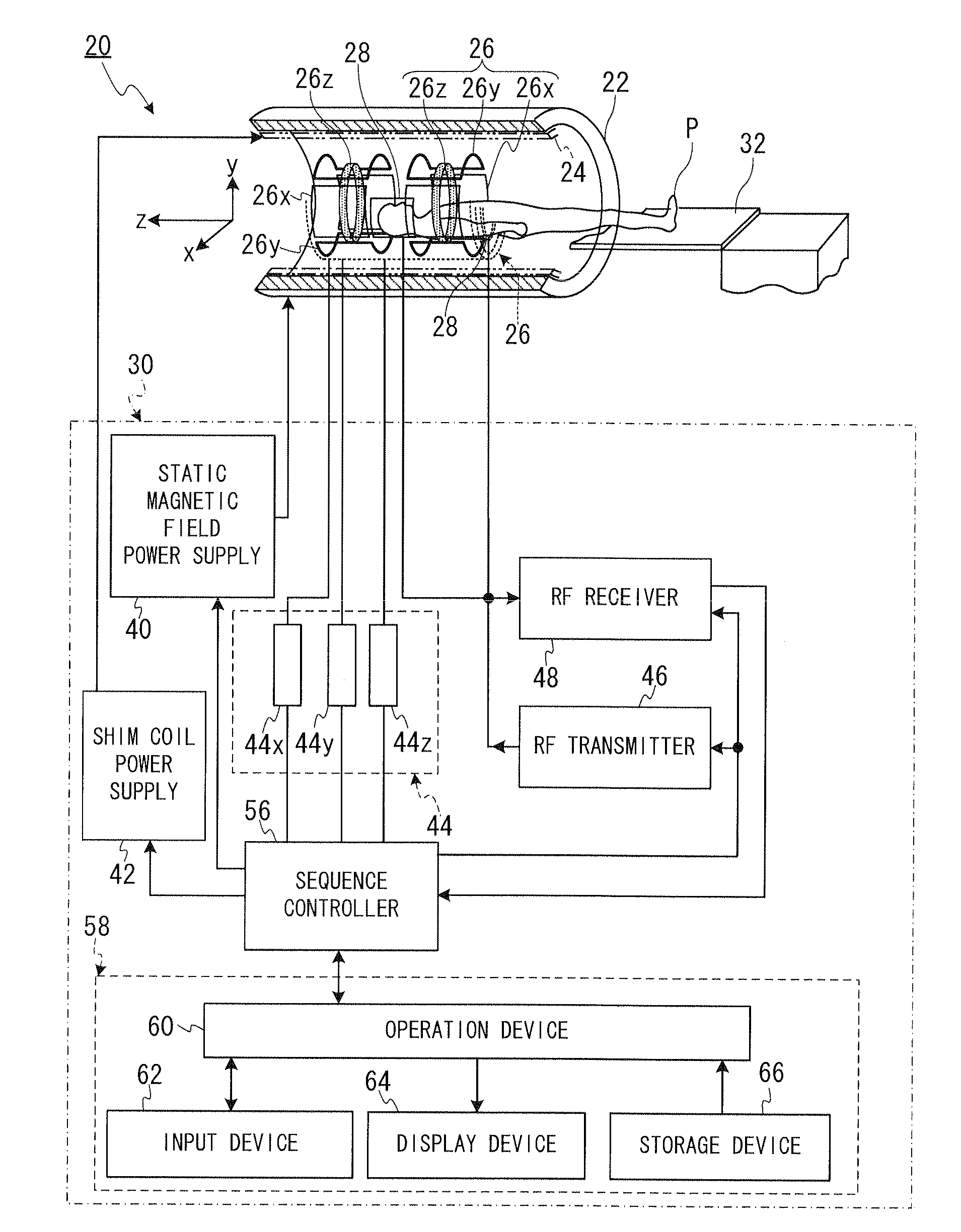
[0047]FIG. 1 is a block diagram showing general structure of the MRI apparatus 20 according to the first embodiment.
[0048]As shown in FIG. 1, the MRI apparatus 20 includes a cylinder-shaped static magnetic field magnet 22 for generating a static magnetic field, a cylinder-shaped shim coil 24 coaxially-arranged inside the static magnetic field magnet 22, a gradient coil (gradient magnetic field coil) 26, RF coils 28, a control device 30, and a bed 32 for placing an object P on it.
[0049]Here, as one example, an apparatus coordinate system, whose X axis, a Y axis and a Z axis are perpendicular to each other, is defined as follows.
[0050]Firstly, the direction of an axis of the static magnetic field magnet 22 and the shim coil 24 is aligned with the direction which is perpendicular to the vertical direction, and the direction of the axis of the static magnetic field magnet 22 and the shim coil 24 is defined as the Z axis direction.
[0051]Additionally, it is assumed that the vertical direc...
second embodiment
[0182]The MRI apparatuses according to the second embodiment and the third embodiment have the same configuration as the MRI apparatus 20 according to the first embodiment. According to the second embodiment, the correction to uniformize the static magnetic field based on the magnetic field correction map is not performed, and only the correction of the phase error is performed. In the following, the second embodiment will be described with regard to the difference from the first embodiment.
[0183]FIG. 12 is a timing chart showing an example of pulse sequences for the main scan and template shots 1 and 2′ in the spin-echo single-shot EPI. In FIG. 12, the definitions of the abscissa axis and the like are the same as those in FIG. 3, and the main scan shown in the upper part of FIG. 12 and the template shot 1 shown in the middle part of FIG. 12 are the same as the main scan and the template shot 1 according to the first embodiment.
[0184]In FIG. 12, only the template shot 2′ (TEMPLATE S...
third embodiment
[0202]According to the third embodiment, as in the first embodiment, the correction to uniformize the static magnetic field based on the magnetic field correction map and the correction of the phase error are performed. In the third embodiment, three template shots are performed. In the following, the third embodiment will be described with regard to the difference from the first embodiment.
[0203]FIG. 14 is a timing chart showing an example of pulse sequences for template shots 1, 2′ and 3 in the spin-echo single-shot EPI. In FIG. 14, the definitions of the abscissa axis and the like are the same as those in FIG. 3.
[0204]The pulse sequences for the main scan according to the third embodiment is the same as “the pulse sequences for the main scan according to the first embodiment” and “the pulse sequences for the template shot 1 according to the third embodiment”, and therefore are not shown in the drawing.
[0205]The template shot 1 (TEMPLATE SHOT 1) shown in the upper part of FIG. 14 ...
PUM
 Abstract
Description
Claims
Application Information
 - R&D Engineer
- R&D Manager
- IP Professional
- Industry Leading Data Capabilities
- Powerful AI technology
- Patent DNA Extraction
Browse by: Latest US Patents, China's latest patents, Technical Efficacy Thesaurus, Application Domain, Technology Topic.
© 2024 PatSnap. All rights reserved.Legal|Privacy policy|Modern Slavery Act Transparency Statement|Sitemap