Antenna module, and touch module and electronic device using the same

a technology of antenna modules and electronic devices, applied in the structural forms of radiating elements, devices with touch pads/sensors/detectors, substation equipment, etc., can solve the problems of crowded inner space of mobile phones, poor structure integrity, and inability to design space allocation of inner parts of mobile phones. , to achieve the effect of reducing the volume space occupied by antenna modules in electronic devices, good structure integrity and relatively simple fabrication

Inactive Publication Date: 2012-06-14
SMART APPROACH
View PDF4 Cites 15 Cited by
  • Summary
  • Abstract
  • Description
  • Claims
  • Application Information

AI Technical Summary

Benefits of technology

[0012]According to the antenna module and the electronic device using the same of the present invention, the antenna circuit is directly formed on the transparent substrate overlapped on the display panel, so the fabrication is relatively simple, and the volume space occupied by the antenna module in the electronic device is reduced. In addition, compared with the difficulties in arranging other electronic elements caused by disposing the antenna circuit on the mother board in the prior art, the antenna module of the present invention can avoid the difficulties encountered in the prior art. Therefore, such an antenna module has good structure integrity, and thus can facilitate the development of the electronic device towards miniaturization and thinning.

Problems solved by technology

In other words, the mobile phone is becoming thinner and more miniature, and thus an inner space of the mobile phone becomes crowded.
Therefore, by using the conventional means of disposing the RFID antenna module inside the mobile phone, a person encounters many difficulties in designing space allocation of inner parts in the mobile phone.

Method used


Image

  • Antenna module, and touch module and electronic device using the same
  • Antenna module, and touch module and electronic device using the same
  • Antenna module, and touch module and electronic device using the same

Examples


Embodiment Construction

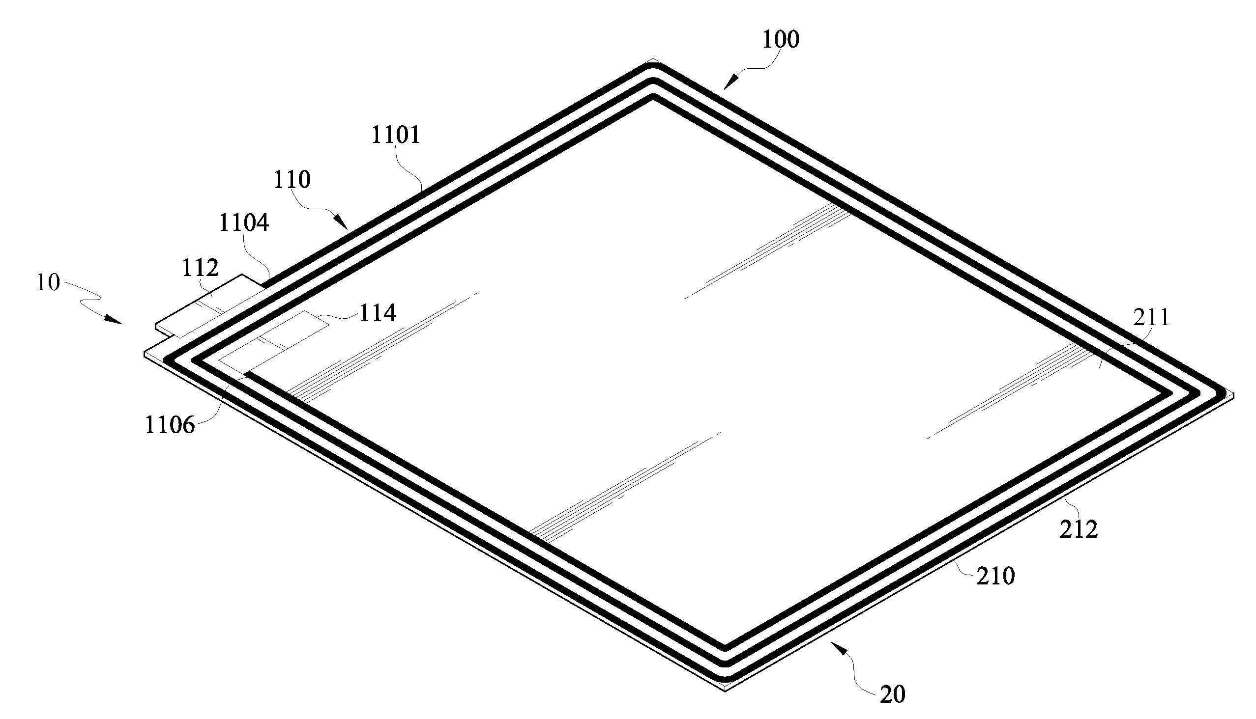
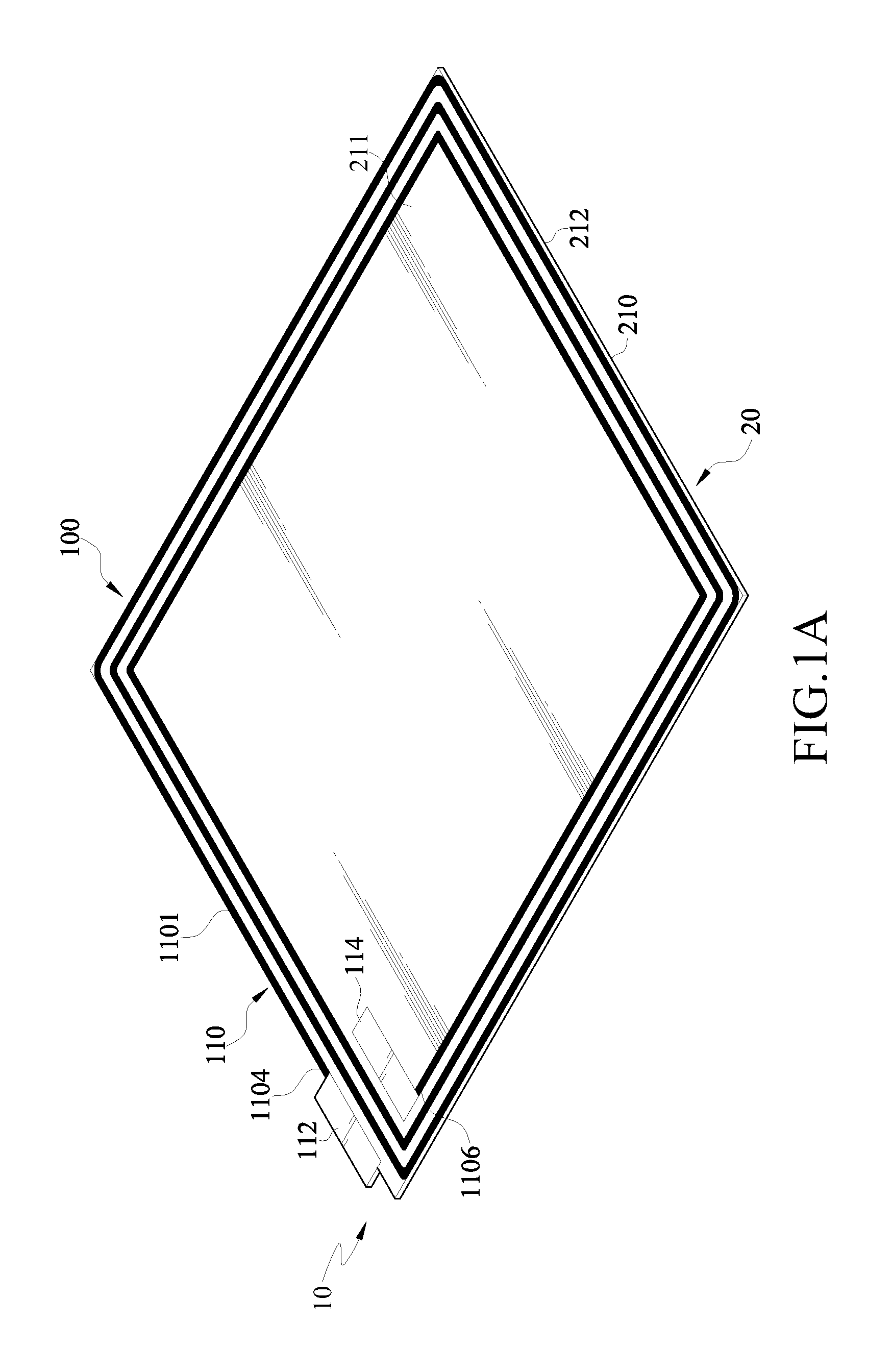
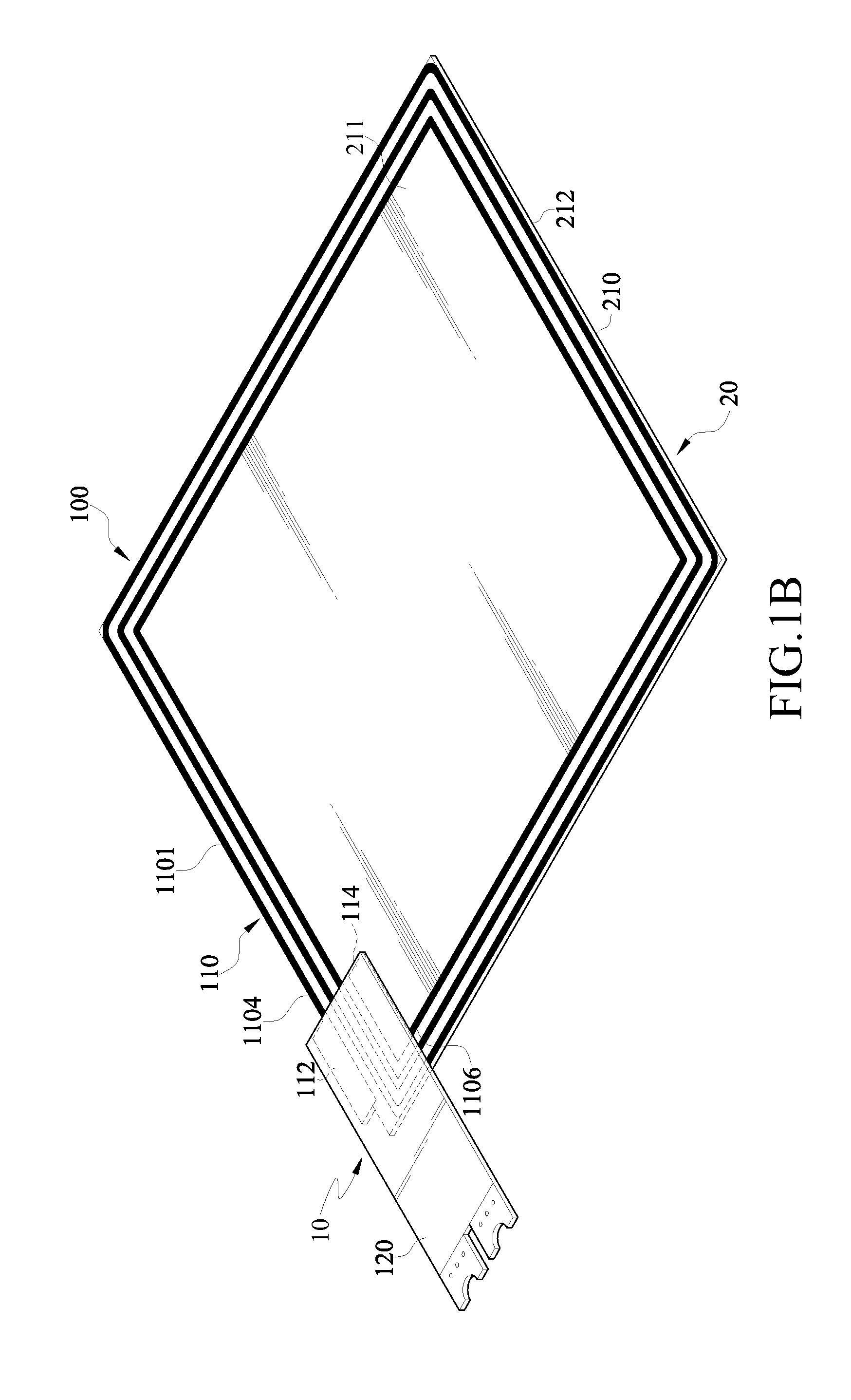
[0020]FIG. 1A is a schematic structural view of an antenna module according to an embodiment of the present invention; and FIG. 1B is a schematic structural view of an antenna module according to another embodiment of the present invention.

[0021]In an embodiment of the present invention, an antenna module 10 comprises a transparent substrate 210 and an antenna circuit 100. The transparent substrate 210 may be a glass substrate and has a rectangular shape, but the present invention is not limited thereto. The antenna circuit 100 is configured on the transparent substrate 210, and comprises a pair of electrodes 112 and 114, and a coil assembly 110. The transparent substrate 210 has a first surface 211 and a second surface 212 opposite to each other.

[0022]The coil assembly 110 is formed on the first surface 211 of the transparent substrate 210, and disposed surrounding a periphery of the first surface 211. In this embodiment, the coil assembly 110 may be formed on the transparent subst...


PUM


Abstract

An antenna module, and a touch module and an electronic device using the same are presented. The antenna module includes a transparent substrate and an antenna circuit disposed on the transparent substrate. The antenna circuit includes a pair of electrodes and a coil assembly connected to the electrodes. The electronic device includes a mother board, a display panel, and an antenna module. The transparent substrate and the mother board are overlapped on opposite surfaces of the display panel, such that a circuit design space of the electronic device using the antenna module is reduced.

Description

CROSS-REFERENCE TO RELATED APPLICATIONS[0001]This non-provisional application claims priority under 35 U.S.C. §119(a) on Patent Application No. 099143297 filed in Taiwan, R.O.C. on Dec. 10, 2010, the entire contents of which are hereby incorporated by reference.BACKGROUND OF THE INVENTION[0002]1. Field of Invention[0003]The present invention relates to an electronic device and an antenna module thereof, and more particularly to an antenna module disposed on a touch panel, and an electronic device using the same.[0004]2. Related Art[0005]Radio Frequency Identification (RFID) technology is a short-distance radio communication technology, and is suitable for use in electronic commerce such as an electronic wallet and an easy card, and identification such as access control.[0006]As described above, some mobile phones currently are equipped with the RFID technology, and thus can provide convenient electronic commerce service such as an electronic wallet and an easy card. Therefore, a use...

Claims


Application Information

Patent Timeline
Patent Type & Authority Applications(United States)
IPC IPC(8): H01Q1/24H01Q1/36H01Q1/22H01Q7/00
CPCH01Q1/2258H01Q1/38H04M2250/22H04M1/0266H01Q7/00
Inventor WANG, CHENG-KE
Owner SMART APPROACH
Why Eureka
Try Eureka